2
07/06/2010
I could now re-asssemble the valve gear and, although very awkward to do, the job went much quicker than expected. I didn't refit the weighshaft at this point as I wanted to look at the valve gear in the simulator. The lifting arms for the suspension levers seemed much shorter than they ought to be and I was interested to see what effect this would have on the valve events. More of that later.
Next, the valve timing had to be reset so this meant removing the valve chest cover of course. That came off fairly easily and I was greeted by the sight of gobs of silicon gasket goo all over the valves. It seems that at some point someone else had had the valves out and refitted them with silicon between the valve bodies and the driving buckles. Not sure why this had been done but I suspect it was to hold the valves against the port face rather than allow them to drop away slightly. So the valves and buckles were removed and all the goo cleaned off before they were refitted.
The valves 'glued' into the buckles with silicon!
I wasn't very impressed with the finish on one of the valve faces. This resembled a ploughed field, and it looks as though the valve was only touching the port face on the four corners. This was soon remedied by rubbing the valve on carborundum paper on the surface plate and, to be on the safe side, I did the other valve as well.
Before refitting the valves and buckles, I extended the thread slightly on the crosshead end of the valve rods so that the valves could be adjusted easily by screwing the crosshead along the rod. I then fitted a thin nut to lock the crosshead in position once the valve was set.
As mentioned above, I wanted to check out the valve gear in a simulator to see what it was like and it turned out to be pretty bad. The gear is based on Pansy which is not a very good design anyway and the fact that the lifting arm on the weighshaft had been shortened for some reason made matters much worse. Putting the dimensions into the Hall simulator showed that there was nearly 30% difference between the cut offs for the front and rear halves of the cylinders.
Original valve gear with lifting arms of 1.563"
I don't know what the actual amount of lead is as this will depend on how the eccentrics have been set so I chose a figure for the advance angle that gave about 0.01" at 50% cut off.
Playing around with the lifting arm length, I found that extending it to 2.07" from the original 1.563" made a huge difference to the symetry of the valve events in forward gear, which was what I was interested in. The loco will spend little time running in reverse on our continuous track!
Valve events with lifting arm extended to 2.07"
So, I decided to make a new weighshaft with a longer lifting arm and give that a try. It was necessary to make the arm 'bent' to clear the bottom of the expansion links in full forward gear but apart from that there were no other problems. I could have modified the original weighshaft but I thought it best to leave that alone and make a completely new one. The original could always be refitted then if the new one did not work out.
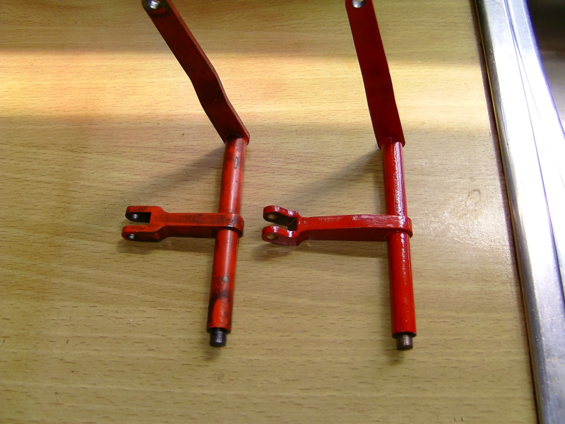
The new weighshaft and the original
The new weighshaft was fitted and then the valves set to give equal leads at about the 50% cut off setting. This was done by 'eye' which is not the best way to do it as it's not really accurate enough. The amount the ports were open was checked when the pistons were at front and dead centre and the valves set to make this as equal as possible. The valve setting was a bit hit and miss anyway as I don't know whether the eccentrics are set properly and I did not want to start messing about with those. It's virtually impossible to get the straps off the eccentrics to adjust them anyway without taking the boiler off so I had to assume that they were correct?
A quick run on air showed promise and the loco ran smoothly and very quietly in forward and reverse gear, although the cut offs in reverse gear are nothing like equal due to the geometry of the valve gear design.
It was now time for a steam test!
I adapted one of my blowers to fit the large bore chimney and fired her up using soaked charcoal and then Welsh steam coal. Everything appeared steam tight and pressure gradually built up to the full working pressure with plenty of draught from the locos own steam blower. Opening the regulator got the wheels turning with a very soft, even beat, so the timing must be reasonably close. It is necessary to open the regulator wider to begin with to seat the valves on the port face but then it can be backed right off. The reverser segment only has two notches for forward gear and two for reverse, one for full gear and one for about 50% cut off I guess. The loco will run ok with the reverser pulled back a bit more so it could have another notch machined I think, certainly in forward gear. It is possible I suppose that originally the loco would not run very well with the reverser notched up any more, hence just the two positions.
There was a bit of a knocking noise coming from the middle of the loco which turned out to be one of the axle boxes on the centre axle having a bit of slop in the horn. This should disappear when the loco is running under load.
There was a rather alarming banging and clattering sound coming from the crosshead pump area which I pinned down to the inlet ball valve bouncing around. It's obviously got far too much lift and is probably not seating at all. Certainly the pump did not seem to be putting water into the boiler even with the bypass fully closed. I think the gland nut for the ram was leaking as well, as a puddle of water appeared under that area of the loco.
The injector flatly refused to pick up and I suspected the water supply. I had tested the injector previously on my test rig and it had worked fine then. I disconnected the loco water feed and connected a separate one from a container of water and the injector picked up straight away and worked well. I suspect the real problem is that the water in the pannier tanks is getting too hot and this is stopping the injector picking up. There's not much that can be done about that unfortunately except run the water from a separate tank on the driving trolley.
The lubricator was pumping way too much oil now that the valve rod from which it is driven was moving it's full amount and the ratchet was clicking over two teeth all the time.
All in all a successful steaming which showed that the loco would now build up and maintain boiler pressure. Just a couple of things to sort out still.
After the loco had cooled down I managed to get the crosshead pump off leaving the ram attached. This was fortunate as it would have been impossible to disconnect the ram without a major strip down. The ram was very loose in the gland packing so that was adjusted to give a nice fit. The ram is ¼" diameter and the stroke is 2" so it should be able to put plenty of water in the boiler. I stripped down the valve boxes and cleaned the balls and the seats. The inlet ball did seem to have a lot of lift (about 1/8") but the only way to cure this would be to make a new bottom fitting. I wanted to take the loco to the club the next day for a proper run and I was running out of time so I just put the pump back together as it was and refitted it in the frames.
I moved the operating rod on the lubricator lever to the next hole down to reduce the travel but I think it will still be too much and may need a new lever making with more adjustment holes in it.
Next day we took the loco to the club track and gave it a proper test run. The owner was also there to watch the events. The loco was soon in steam but the problems with the injector meant having to use the hand pump all the time to maintain the water level which was a pain. I finished up with a blister on my thumb from all the pumping! I think it really needs a larger bore pump.
I was hoping that once running on the track it would be possible to use the crosshead pump to maintain the water but unfortnately this still didn't seem to work so we had to rely on the hand pump all the time. This meant filling the boiler, doing a lap of the track, and then stopping for a refill. We could get the injector to work occasionally but only by flooding the tanks with cold water to cool them down. We did eventually swap the injector for the one off my brother's Rob Roy which did work much better, although with a lot of water from the overflow all the time. I think the original injector needs the steam cone shimming out a bit to increase the water flow through the injector. I'll try this on the test rig later.
The loco ran very well indeed, very quiet and very smooth, on just a touch of regulator. It still needed a bit more regulator when starting off to seat the valves, but once moving, the regulator could be virtually closed. We all did a few laps on it and towards the end, the owner was going around like a bat out of hell! He was really chuffed to have it running again. I reckon it's probably running much better now than it ever did due to the 'improvements in the valve gear etc. Towards the end of the day, the crosshead pump did seem to be doing something as we managed three laps without stopping, but it still needs looking at.
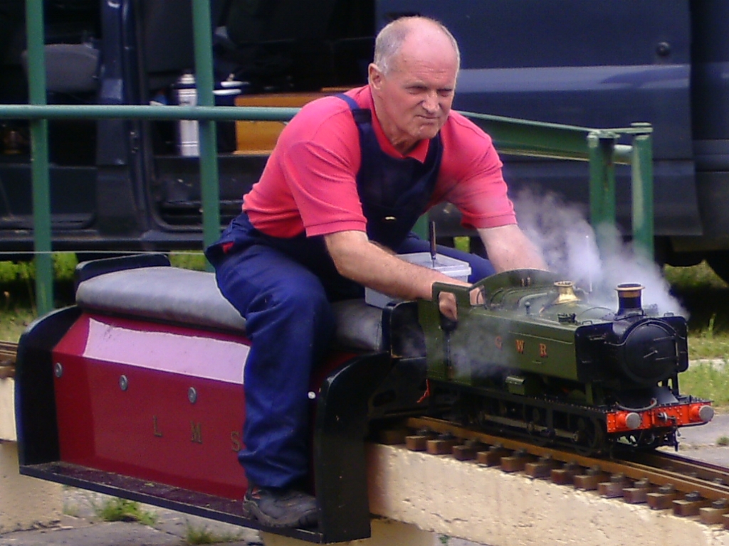
John, the owner, at speed. Got to love that look of determination on his face!
I've brought the loco back home again to try and sort out the crosshead pump and the injector which I hope to do in the next day or so. The lubricator is still over lubricating so that needs sorting as well. My glasses were completely covered in oil after just one lap!
21/06/2010
Once the loco was on the bench again, the crosshead pump was removed and I had a good look at the valves. Blowing through the inlet connection showed that the ball was virtually sealing off the drilled hole through to the pump bore when it lifted to it's full height. I removed the bottom fitting and it was obvious that although the top of the ball housing had a slight nick in it to allow the water to pass when the ball lifted, it was nowhere near deep enough. I sorted that problem out by milling two deep slots in the housing with a 1/8" diameter end mill. I also reduced the lift of the ball by milling about 1/16" off the bottom of the pump casting which the water inlet fitting screws into.
The pump was refitted and next I had a go at the injector. I shimmed the steam cone further out from the body by 0.01" and tried the injector on the test rig using warm water in the water tank rather than cold. The injector seemed to work reasonably well with a water temperature up to 50°C so I left it at that and refitted it.
I decided to have another look at the hand pump as it didn't seem to be working very well which meant removing it again from the side tank. It took ages this time around, probably because there were now four screws holding it in rather than just two!
Having got it out I removed the ram to find that the new O ring I had fitted last time had split. It had been an unknown type from a box bought at the Pound Shop so could have been made from anything I suppose!
The ram was a bit of a sloppy fit so I decided to make a new one. Checking the bore of the body showed that it was tapered towards the outlet end so I reamed it again with a 1/2" reamer and then lapped it with some fine abrasive paper wrapped around a bit of rod (ala LBSC!). I didn't have any 1/2" stainless to hand so made the new ram out of PTFE which I had plenty of. I fitted two silicon O rings this time for good measure, rebuilt the pump, and fitted it back into the tank.
While I was at it, I removed the reverser quadrants and milled another slot for forward gear which should give a cut off of about 30% according to the CAD drawing I had made earlier for the valve gear.
I gave the loco another steam test before taking it to the track again and everything seemed to be ok. The crosshead pump worked very well, although still a little noisy. Even the injector worked this time!
Next day was the Club members running day but before taking the loco there, I altered the position of the drive rod on the lubricator arm so that when the valve gear was notched up, the ratchet just clicked around by one tooth.
We had a good days running at the track apart from the damned injector which refused to work again! Must be the Coalville water I think!
The crosshead pump was more than man enough to maintain the water level and we managed lap after lap without needing the injector fortunately. The hand pump is much better than before and you don't need to pump like crazy to get any water into the boiler. The loco will pull away easily with two people on a passenger truck with the reverser in the new notch in the quadrant. It does 'kick' a little until you get going but runs well after that. I suspect that the lead may be a bit excessive at this cut off position which would have this effect at slow speeds.
All in all, it's a very nice loco to drive and the owner is very pleased with it. I have suggested that he should bring it down to the track as often as possible so that I can have a drive! It's so relaxing to drive compared to 2½" gauge locos!
23/12/2011
The loco came back to me a few months ago for some alterations at my suggestion. On it's last run at the club the handpump in the side tank packed up when the ram came out of the body due to some over enthusiast pumping (not by me!). I suggested fitting a new larger capacity pump in the rear bunker as the old one was inadequate for the size of the boiler and a real pain to get at if it needed to be removed.
Having studied the job, I decided there was room to fit a vertical pump of 3/4 inch bore and 1 inch stroke. I went for a vertical pump rather than the usual horizontal one because it was then possible for the handle to 'waggle' backwards and forwards rather than side to side. This means the loco doesn't rock from side to side when you use the pump! I also took the opportunity to fit a new injector water valve of larger bore, also in the rear bunker where it would be much easier to operate. The original was in the 'prototypical' horizontal position under the side tank which meant the operating shaft was only just above the cab floor and very difficult to use.
Unfortunately, I didn't take any photos during construction of the various bits but here's one of the pump and injector valve when they were being fitted:
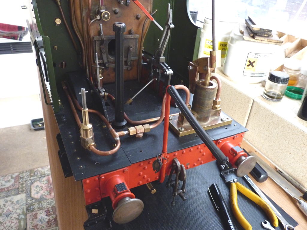
The pump body was fabricated from a bit of cored gunmetal bar and various bits of brass, all silver soldered together. The ram is turned from PTFE and is fitted with an O ring. The injector valve is a 90 degree job with a PTFE valve. I prefer the simple 90 degree turn type over the scew type valves - much quicker action. During the 're-plumbing' I included a pipe under the rear buffer beam which will allow a water feed from a separate tank on the driving trolly which will benefit the injector. The water in the side tanks soon gets too hot for the injector to work unless you keep filling the tanks with cold water all the time.
Once all the platework was refitted, I made a plate that sits in the top of the rear bunker and hides all the 'gubbins' underneath. This plate has a slot for the handpump handle and a hole for the injector valve shaft.
Another job I did was to get rid of the separate clacks for the top feeds and incorporate the clacks into the top feed fittings where the balls are easy to get at if they need attention. The original clacks were behind the side tanks and impossible to get at without removing the tanks. I think half the trouble with the injector had been the ball sticking in the clack due to our Coalville water which has a lot of minerals in it. Altering the top feeds was just a matter of machining some seats in the housings and fitting a ball. Not sure why this was not done to begin with?
Once everything was completed, I gave the boiler a hydraulic test to check all the fittings etc. I couldn't get the regulator to seal against hydraulic pressure so eventually had to disconnect the steam pipes inside the smokebox and blank them off there. I also gave the loco a quick steam test to check the clacks and the injector which seems to work much better now for some reason. Perhaps the new water valve has improved the water flow?
One last thing was to make a cover for the horrible gash in the top of the side tank where the old pump used to fit. It really wants filling in permanently but this would involve a repaint job which is maybe something for the future when the loco starts looking a bit tatty.
The loco is now back with it's owner and we are hoping for a steam up on New Years Day. I'll try and remember to get some more photos then.
31/01/2012
Well, we gave the loco a run on New Year's Day and had problems with the steaming. We struggled to keep up steam pressure around the track and suspected that the coal we were using may not have been very good. Things did improve if it was driven fast rather than slow. The loco ran well apart from that and the new hand pump worked well. The injector seemed to work more reliably than before and I think that the new water valve may give better flow than the old one.
We had another go last Thursday with even worse results! The fire just would not pull up with the steam blower and it took my brother and the owner ages to get it going. I was busy running a Polly 3 that I had taken back after resetting the valves and gluing the wheels back on! The original Loctite had failed eventually, probably due to a lack of cleanliness when the wheels were originally fitted to the axles.
I eventually had a look at the 94XX and it was obvious that the blower was not doing a great deal. The electric blower pulled the fire just fine but it just died again when the steam blower was used. I opened the smokebox door when the blower was on and it was obvious that it had got knocked out of alignment (it's just a jet on the end of a bit of tube) and the jet was hitting the bottom of the peticote pipe rather than going up the chimney. A quick tweek with pliers sorted that out and the blower worked much better, although not as well as it should. We eventually got the loco on the track but I only got halfway around the track before the pressure dropped towards zero. We called it a day and the loco finished up back in the car and back at my house!
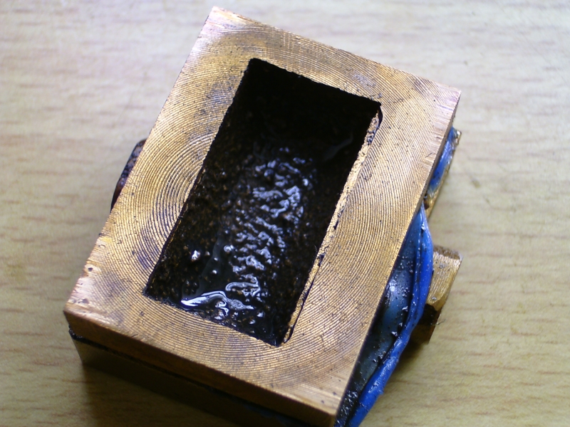
Although the loco had run quite well last year, I suspected that the draughting was not all it should be. The chimney is very big at 1.375" internal diameter and I had a feeling that the steam cone from the blast nozzle was perhaps not filling the chimney, allowing air to be sucked in around the outside, destroying the smokebox vacuum. I took some measurements, drew everything out in CAD, and compared the results with the diagrams devised by Harold Barton and described in Model Engineer. The blast nozzle is 0.25" diameter which is correct for 1.5" diameter cylinders (16% of the cylinder diameter) but the 16% steam cone hits the inside of the chimney over halfway up the inside which was far too high. Harold's results show that the steam cone wants to hit the inside of the chimney at a height of between 7 and 10 times the diameter of the blast nozzle. The arrangement at the moment gives a height of 16 times the blast nozzle diameter. Harold suggests that at this height, the steam has very little energy left to create a suitable vacuum.
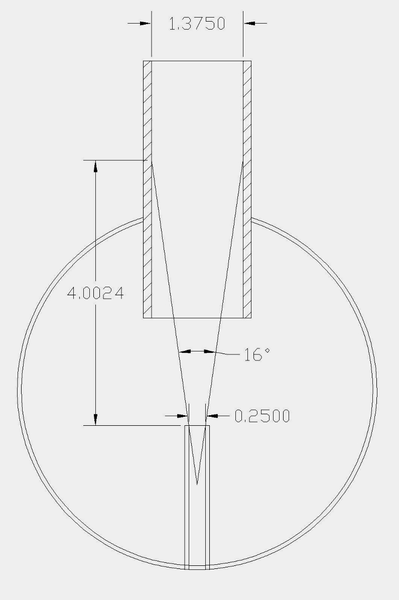
Original draughting
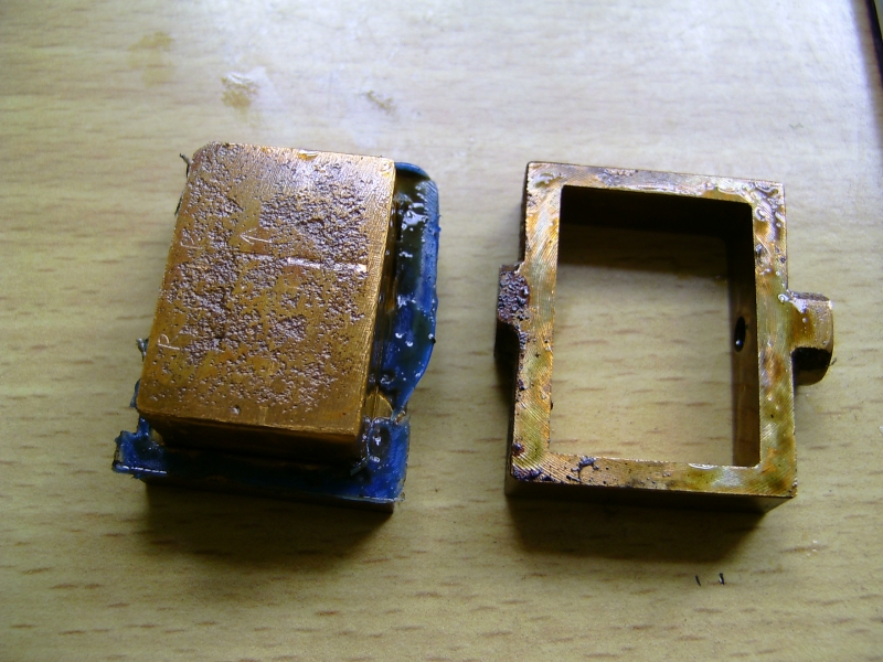
I drew up a new design using a liner fitted inside the original straight chimney to reduce the choke of the chimney (the narrowest part) and with a 2.5 dgree taper from the choke upwards and a flare at the bottom. This reduced the height where the steam cone hit the choke down to 9 times the nozzle diameter, a more acceptable figure (hopefully!). This also reduced the diameter of the choke from 1.375" to 0.885"
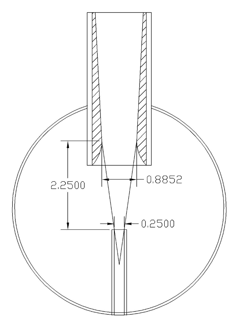
New draughting design
The only bit of bar I had of a suitable diameter to make the new liner was a length of aluminium so I used that. It can always be replaced at a later date if necessary. Unfortunately, it wasn't quite long enough so the new liner does not reach to the top of the old chimney. The reduced diameter of the choke should also make the blower more effective as I am sure that the tiny jet could never have filled the original chimney.
Once the liner was fitted, I did check the alignment of the blast nozzle by putting a length of 0.25" bar in the hole and it was actually pointing to one side instead of straight up. This was sorted by 'bending' the blast pipe until the bar was central in the chimney. The fact that it was out of alignment would not have helped the original draughting, especially if it was not very good to begin with.
At this point I decided to give the loco a steam test with it on blocks so it could be run. The blower did seem to work a lot better and the fire burned very well when the loco was running, easily maintaining pressure when just ticking over.
One thing I noticed when refitting the ashpan and grate after cleaning the fire at the end of the run was that the grate seemed a bit too long to fit inside the bottom of the firebox. If you didn't get it spot on when refitting, the front of the grate caught on the foundation ring and tipped the grate up, leaving the back too high inside the firebox and probably leaving a gap at the back. I had noticed when raking the fire, this time and at the track, that quite big lumps of burning coal fell out the ashpan. This could be because the grate wasn't fitting properly. I cut a bit off the front of the grate and this seems to have cured that problem. I seem to remember that the owner has two different grates for this loco and the other one may well be shorter. Possibly they have got swapped over.
I'll be taking the loco back to the club on Thursday and hopefully we will have another run and see what happens this time.
03/02/2012
We took the loco to the club yesterday and ran for a couple of hours. The loco is totally transformed and steams like a witch now! It only took 10 minutes to get steam up and I reckon that the grate not fitting properly was the main reason for the very poor results last time. The blower works well and we had no trouble keeping pressure up driving around the track. The safety valves were blowing most of the time, even with the crosshead pump on.The owner is well chuffed and so am I! Hopefully the loco is now sorted and we'll be seeing it at the track on a regular basis now.