GWR 2-6-0 Mogul (sort of!)
2
11/6/2015
I've had a couple of days away from the Mogul to work on a friends 2½" gauge Fayette. I actually brought it home to do a boiler test on it but took the opportunity to try and sort out the valve gear as well. It had never run properly and we always struggled to get it to make one lap of the track. I stripped down the cylinders, recut the ports to clean them up as they were a bit of a mess and made new valves for it. I did a few other bits but really the valve gear (Baker) needs replacing as it has a lot of play everywhere but I didn't have the time or the inclination to do it this time. Anyway, I retimed the valves and it seems to run quite well on air now so we'll see what happens on our 2½" gauge running day on the 27th of this month.
Back to the Mogul!
I've machined the new plugs for the eccentric bores and glued them in with the new Loctite. This time machining the new bores went ok apart from me having a senior moment and machining the first bore too large! That meant removing the plug, making a new one, and starting again. Fortunately, the other three bores went ok first time.
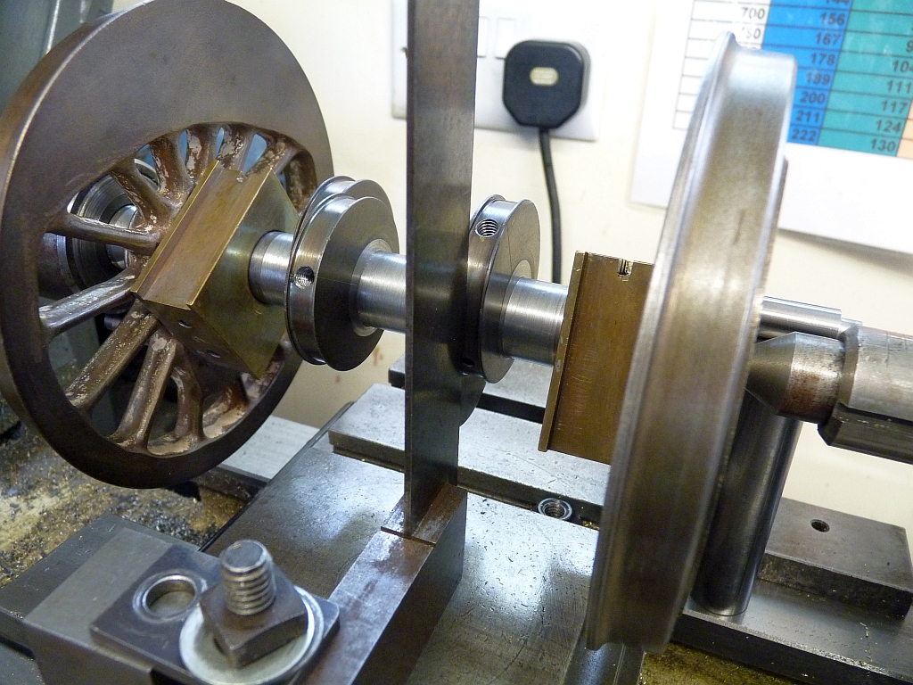
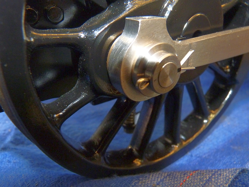
I refitted the eccentrics to the axle, Loctited the wheel back on, and it was time to set the eccentrics to the correct angle. I always try and set the eccentrics on the axle before refitting it to the chassis. This is a far more accurate way than the LBSC/Martin Evans way of setting the eccentrics on the chassis by rotating them until the valve is just opening the ports when the piston is at front and back dead centres. However, you need to know what the angle of advance of the eccentrics needs to be and most designs don't give you this information, probably because the designer may not have had the means to accurately determine it. I've already put the Firefly valve gear into one of the valve gear simulators and modified it to suit the Mogul and determined that the angle of advance of the eccentrics needs to be 114° or 90° plus 24°. I then drew out the eccentric position in a CAD drawing which gives me the dimensions to set the eccentrics in a jig, in my case the lathe.
The way I do the setting is to put the axle between centres in the lathe and then make a spacer to go between the crankpin and the lathe bed of such a length that the crankpin is exactly horizontally in line with the lathe centres. I then clamp a try square to the cross slide and use this as a stop to locate the forward edge of the eccentric. The position of the stop is measured from the axle using the dial on the cross slide, this distance being determined from the CAD drawing.
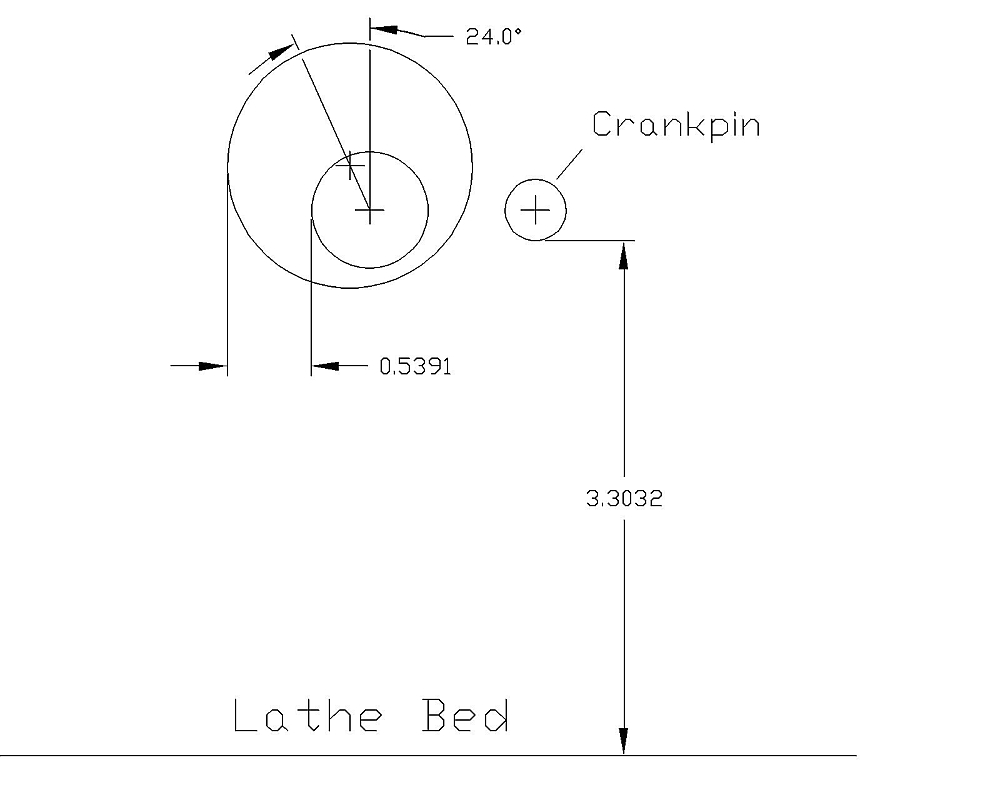
The drawing shows the eccentric on the axle with the centre of the eccentric rotated to give the angle of advance relative to the crankpin, in this case 90° plus 24° or 114°. The lathe (my ML7) has a centre height of 3.5" and the diameter of the crankpin is 10mm or 0.3937". Half the diameter of the crankpin is 0.19685" so the spacer to make the crankpin horizontal to the centre of the axle is 3.5 minus 0.19685 or 3.30315". 3.303 will be accurate enough!
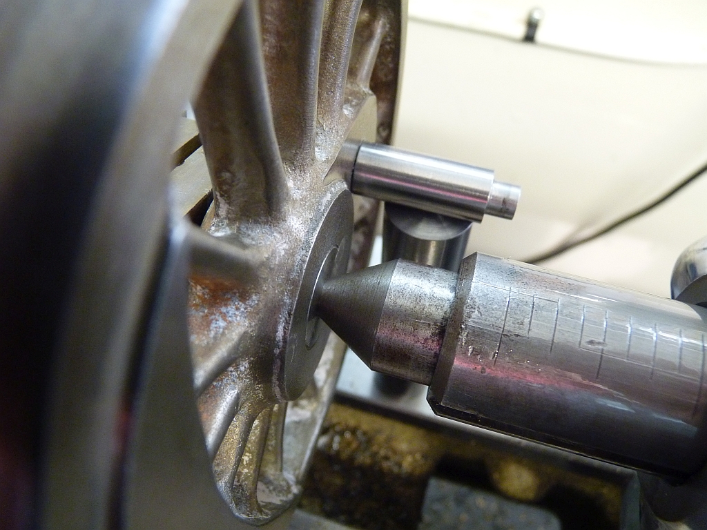
Spacer between bed and crankpin to set the height of the crankpin
With the eccentric rotated by 114° relative to the crankpin, the leading edge of the eccentric is 0.539" away from the edge of the axle and that is the distance away from the axle that our stop, or try square must be.
The first thing is to set the try square so that it is touching the axle. If you have adjustable dials then just set the dial to zero. I haven't, my dials are fixed, so I set the dial to zero first and then move the try square until it touches the axle before clamping it firmly to the cross slide.
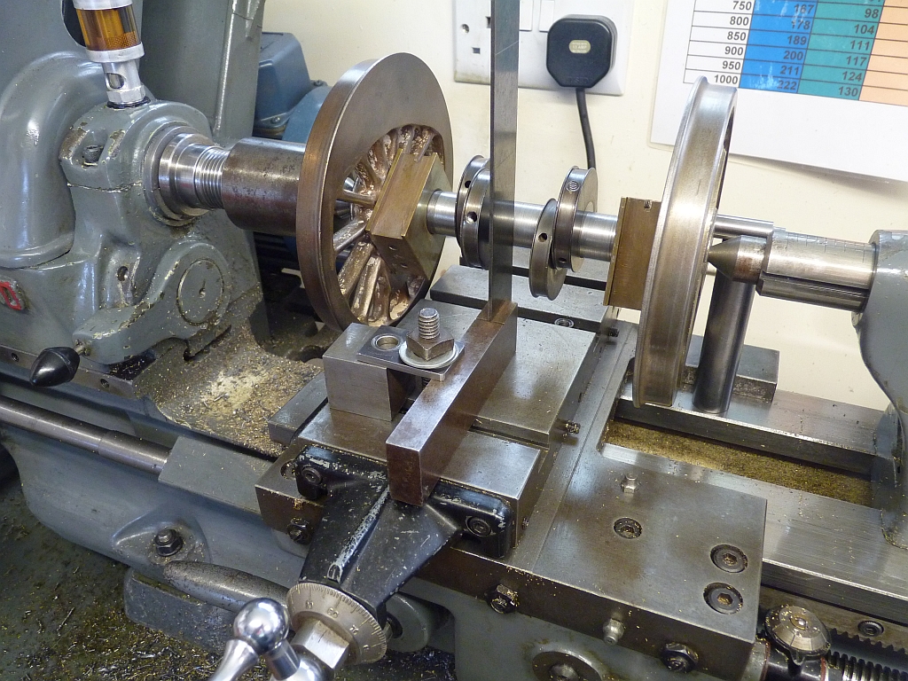
Zeroing the cross slide dial when the try square is touching the axle.
Next, the cross slide is wound out the distance required to position the edge of the eccentric, in my case 0.539". The saddle is moved so that the try square aligns with the middle of the eccentric. The eccentric can then be rotated until it touches the edge of the try square and locked in position by the grub screw/s. Make sure the crankpin is resting on the spacer so that it is in the correct position when adjusting the eccentric!
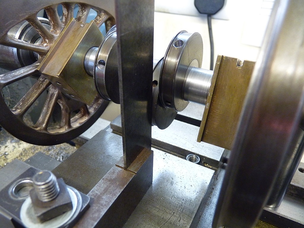
Rotating the eccentric until it touches the try square
The procedure is then repeated for the other 3 eccentrics and job done.
Setting the second eccentric
I had to move the try square from one side of the cross slide to the other to reach all 4 eccentrics as the sideways travel of the cross slide was limited by the fact it was higher than the rim of the wheels so could only move between them.
It probably all sounds very complicated but it's actually very simple and quick to do. It is only possible though if you do know the angle of advance of the eccentric. If the information isn't given on the drawings then you will have to put the valve gear into a simulator to determine the angle. The angle determines the amount of lead that the valve gives so you need to decide how much lead you want at say 50% cut off. I usually go for 0.010" and vary the angle in the simulator until I get that.
I wasn't sure which of the pair of eccentrics should be the forward gear one and which should be the reverse gear so looked at the Firefly drawings. Martin shows the forward gear eccentric as the one nearest the wheel so I followed that. However, I think the Mogul had them the other way around with the reverse eccentric nearest the wheel. That's good actually as it means the new position of the grub screws won't clash with the old dimples in the axle. I don't think it really matters which way around the eccentrics go so long as the forward eccentric strap connects to the top of the expansion link and the reverse to the bottom?
I'm not going to drill the axle and refit the locking pins just yet. I'll wait until I've assembled the valve gear so that I can check that everything is ok before I do that..
Last night I stripped the pony truck down and stripped all the paint off. I noticed that one wheel hadn't been fitted all the way onto the axle so the gauge was about 0.125" wider than it should have been. Maybe the Loctite went off too quick and caught the builder out when it was first fitted? That wheel was removed using the heat treatment and then glued back on correctly.
Now that the eccentrics are finally sorted I've taken the chassis, wheels, pony truck and brake bits to the club today so the chap doing the painting can take them and do his magic on them. Should get them back next Thursday so I can then start putting the wheels back on the chassis and fitting the valve gear.
It looks as though the new tender body won't be available for about 6 weeks so plenty of time to get everything else sorted and back together before I have to build that.
19/06/2015
I haven't done anything on the Mogul for the last week due to finishing work on the Kingette but today I cleaned up the port faces in the shaping machine. The pitting was worse than I thought and I had to remove about 0.020" to get rid of it all.
The shaping machine doing it's stuff
Perfect! Try getting that finish with a milling machine
Shapers are brilliant! Every workshop should have one.
The cast iron for the new pistons and valves arrived yesterday from Macc Models - brilliant service and a good price as well (apart from the postage!)
20/06/2015
I spent last night and this afternoon making the new pistons. The cast iron bar is nice stuff to machine but messy, as is all cast iron. I rough turned the piston blanks oversize and then finish turned them to size after mounting them on the rods. That way you ensure that the piston is concentric with the rod.
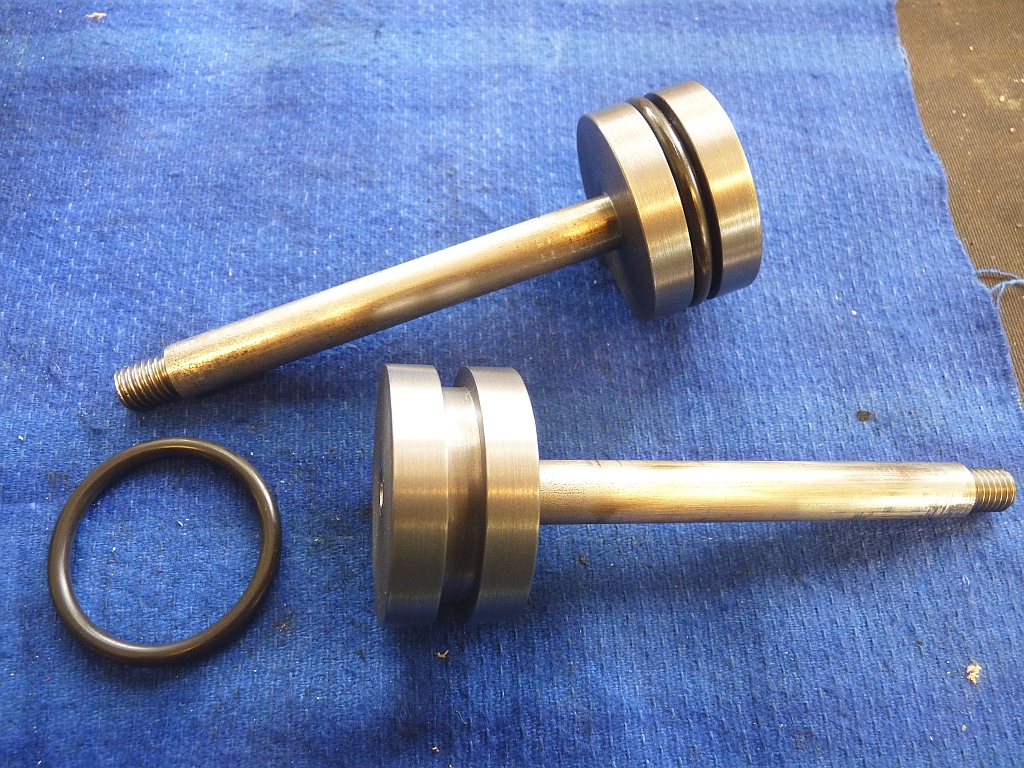
I initially machined the groove for the O ring to the maximum depth as given in the O ring data sheets, which was 0.125". This is what the grooves in the original pistons were sized at. The O rings are listed as 0.125" ( 3.175mm) cross section but actually they are larger than this at 0.139" (3.53mm) so they have to be compressed by 0.014". This made the O ring much too tight in the bore so I eventually made the groove another 0.005" deeper to reduce the compression on the ring. You actually need very little compression on the rings for our use as the pressures involved are low compared to what the data sheets cater for. A lot of people make the mistake of making them much too tight. Also the Viton rings are harder than silicon so are more difficult to compress.
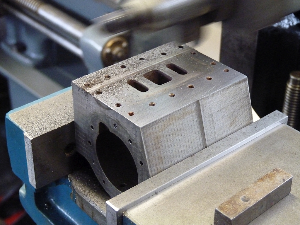
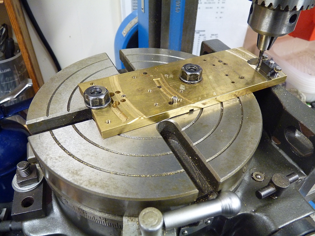
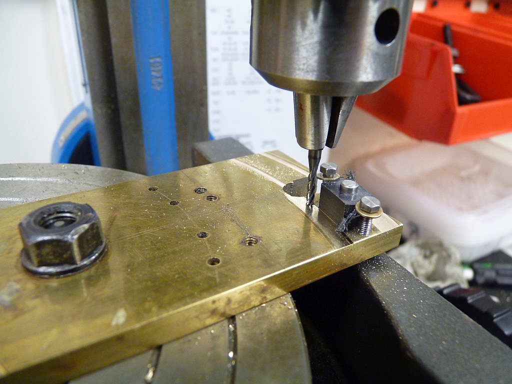
This evening I decided to try enlarging the steam passages between the ports and the cylinder bore. They were originally just two No. 30 holes ( about 0.129") which doesn't give much area for a 1.5" bore cylinder. One of the holes could be enlarged quite a bit but the other was rather close to the bore so that was only taken up a couple of drill sizes. On one end of one cylinder the hole was very close to the bore so that had to be left as it was.
To line the holes up for drilling I used my new digital angle gauge. I've had it for some time (in fact I've finished up with two of them!) but haven't actually used it for anything yet.
I inserted a No. 30 drill down one of the holes and then clamped the cylinder in the milling machine vice with the angle gauge against the drill and adjusted the cylinder until the gauge read 90°. The gauge has magnets on the bottom so attaches itself nicely and doesn't need holding.
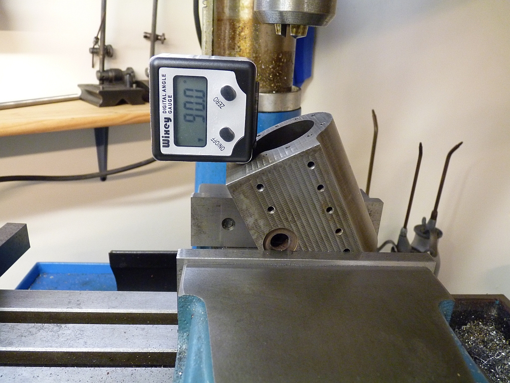
I could have done it just a easily by holding the end of the drill in the chuck whilst tightening the vice I suppose but at least now I've used the angle gauge at last!
The holes nearest the bore were then drilled out to number 27 (0.144") which was the largest I dare go but the second hole was taken out to Number 18 (0.170"). The second hole now overlapped the smaller one so the two holes are actually joined. I could have milled or filed out the metal between the holes to make the passage oval I suppose but as it is I've probably doubled the original area of the passages.
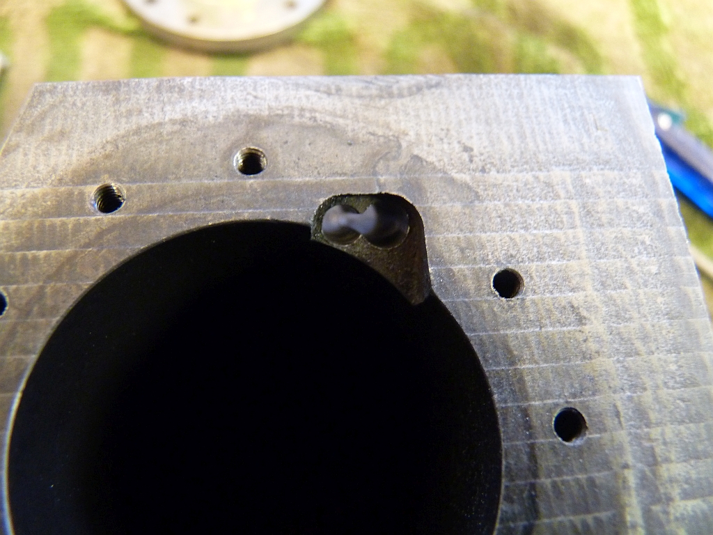
I then cleaned out all the threaded holes with a tap and blew everything out with the airgun ready for reassembly.
New gaskets were made for the cylinder end covers and the rear covers fitted onto the cylinders. The spigots on the covers are a bit of a sloppy fit in the bores (should I be surprised?) so the covers don't centre themselves automatically. I had to move them around slightly until the piston moved freely when it was at that end of the cylinder indicating the cover was properly aligned with the bore. I haven't fitted the O rings to the pistons yet as it will be easier to check the crosshead/slidebar alignment if the piston is free to move in the bore without the drag of the O ring.
24/08/2015
I've been neglecting to keep this rebuild up to date so I'll catch up over the next week or so as I get time on the computer.
I refitted the wheels and axles to the newly painted chassis and found a problem I hadn't forseen. After fitting the wheel assemblies I noticed the centre axle with the eccentrics had far too much side to side play. I mentioned earlier that the centre of the axles was a larger diameter than the ends? It turns out that it's the distance between the shoulder on the larger centre part of the axle and inside of the axle box that determines the sideways movement of the axles and not the distance between the wheel boss and the axle box which is the normal way of doing it. I'd got rid of this shoulder by turning the centre part of the axle down. If I had realised this before I had refitted the wheels to the axle I could have simply turned up some spacers to go between the eccentrics and the axle boxes. I didn't fancy removing the wheels yet again, especially as they had been painted, so I made some split collars instead held onto the axle with screws.
(photo)
Time to start rebuilding and modifying the valve gear,
First job was to shorten the eccentric rods to the correct length. This just involved cutting about 0.75" off the end that bolts to the eccentric strap, redrilling and tapping the hole for the fixing bolt, and then rounding the end off again. I did that using filing buttons.
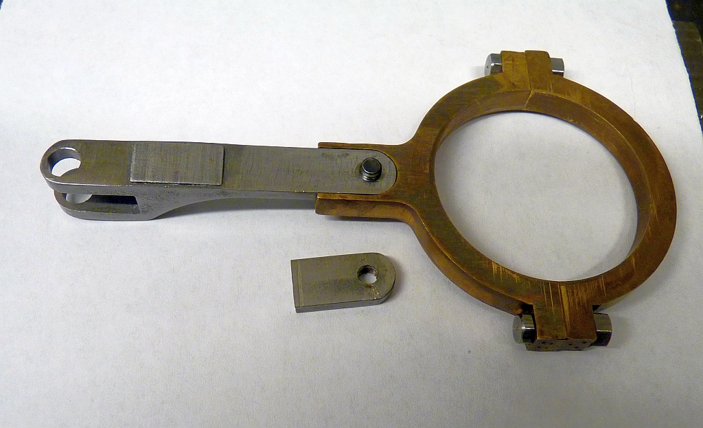
You can see by how much they were too long by the cut off piece underneath the assembled rod and strap!
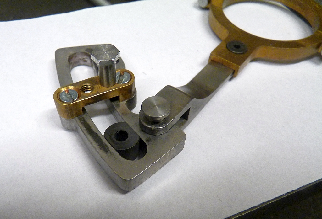
The holes for the pins that fasten the expansion link to the eccentric rods were all worn so I reamed them out to the next size up and machined new pins from Silver steel.
The die blocks were all shapes and well and truly worn so they were replaced with ones made from bearing grade PEEK. These were machined from bits of rod using my fixture for the rotary table.
The piece of brass I used was only just long enough to get the correct radius for these. It's getting a bit worse for wear now!
I machined the die blocks individually so I had to use a couple of bolts on the edges to stop them rotating while they were machined.
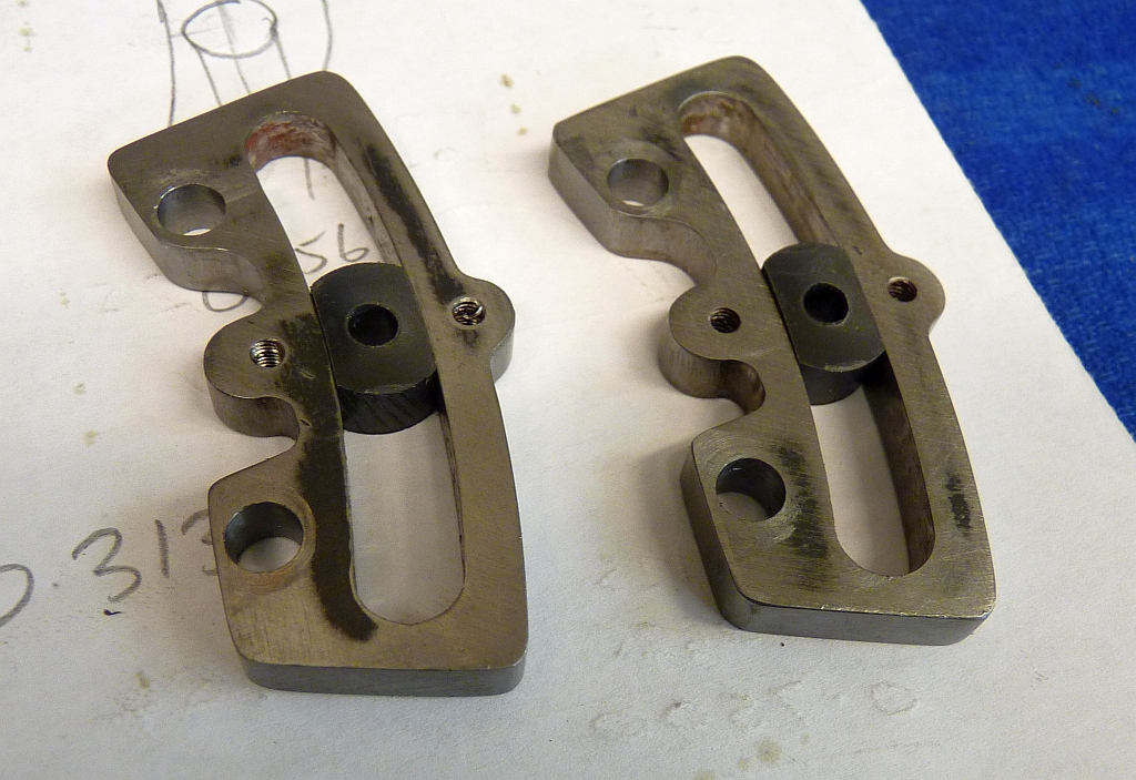
The slots in the expansion links are not worn evenly and the die blocks are a bit loose in the end of the slot used for forward gear but fine at the other end which was the reverse position. The links were glass hard so I didn't fancy trying to remachine the slots so I'll simply turn the links the other way around on reassembly so the unworn part of the slot is used for forward gear instead of reverse.
The position of the suspension pin on the expansion links needed to be moved further out from the centre of the slot. I turned the mounting brackets the other way around so the original threaded hole for the suspension pin was on the forward end of the bracket and there was just enough room to drill a new hole in the rear of the bracket without breaking into the bolt hole that fastens the bracket to the expansion link. I did have to fit the countersunk fixing screw first before drilling and tapping the new hole as it does overlap the head of the screw slightly.
New position for the suspension pin
The original suspension pins were pretty worn so they were replaced with new ones using my favourate method of a silver steel hollow pin with a bolt through it. Much easier than machining from the solid.
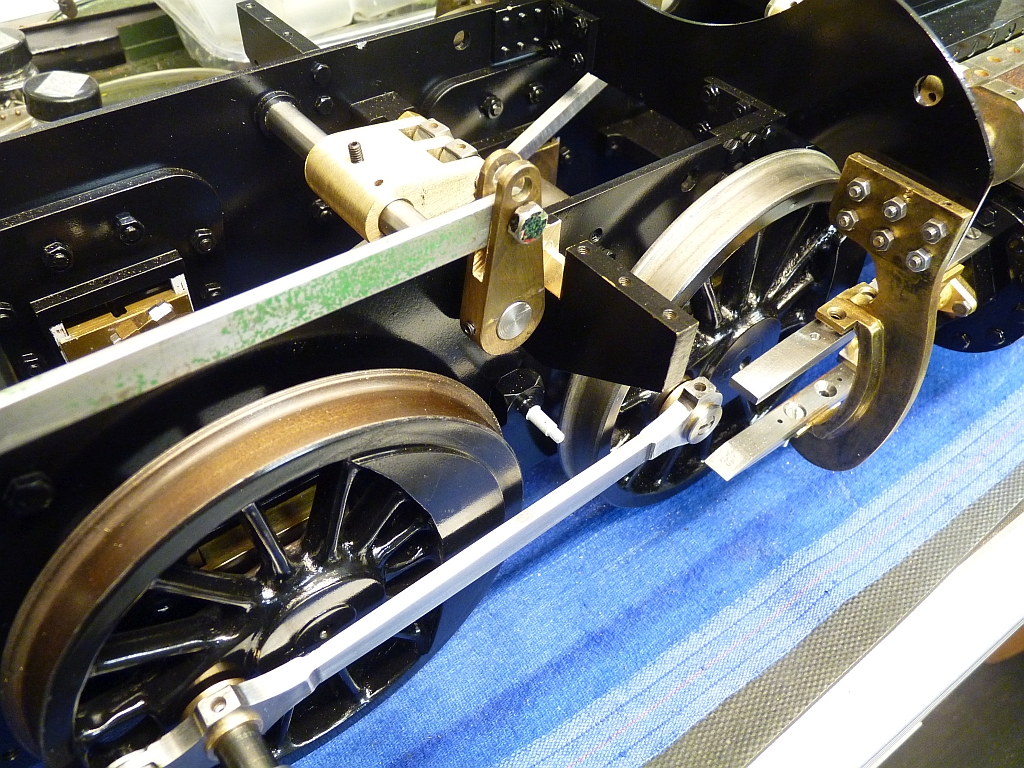
Because I have shortened the eccentric rods, the expansion links are now in their correct position further back in the frames. This meant that the rods that connect to the die blocks and the rocker arms were now too short and had to be replaced. New ones were made by milling them from 0.375" square mild steel.
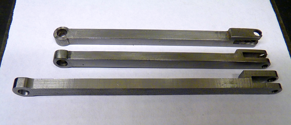
New rod against the old ones
In the above photo the new rod still needs cleaning up.
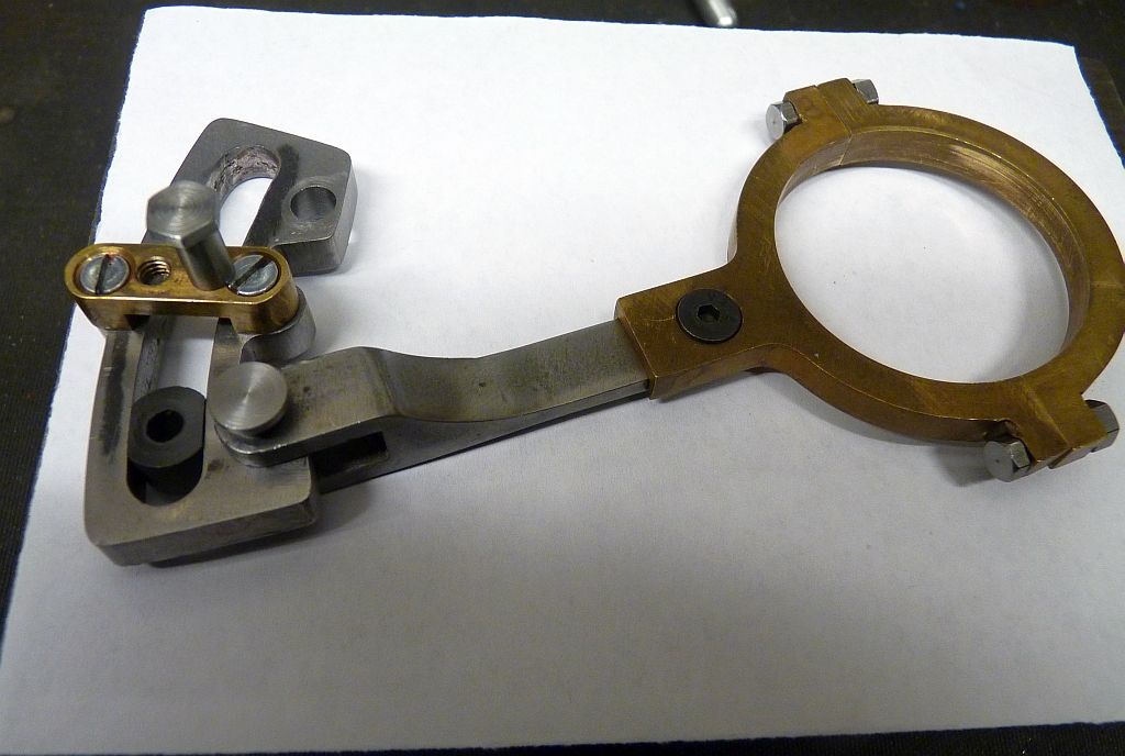
To check everything so far I did a trial assembly of one side of the valve gear.
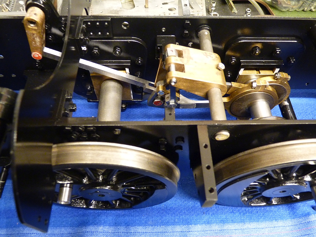
Just noticed on the photo that the rocker rod looks quite close to the leading axle. Better check that next time I'm in the workshop!
25/09/2015
Time for a bit more catching up with the write up!
The other side of the valve gear was assembled and the whole assembly checked for possible jams or clashes by pushing the chassis up and down the bench (no, I didn't make choo choo noises as I was doing it!).
Everything seemed ok so I decided to have a go at the coupling rods next.
These were a bit of a mess and needed a lot of cleaning up with rotary sanding drums to get them reasonable. The knuckle joints were a terrible fit and really loose so I remachined the bores of the joints and made new silver steel pins to fit. They are nice and snug now with no play.
One of the rear coupling rods didn't have an oil box on the top of the crankpin bush, just an oil hole. There was also an oil hole on the underneath of the rod (!) and I suspect that the kit may have been supplied with two rods the same instead of a left hand and a right hand one. Whoever built it must have decided to use the wrong one anyway and filed the original oil box off which would have been on the bottom rather than the top! I silver soldered a block of steel onto the rod to replace the missing oil box and filed it to shape.
Can't see the join!
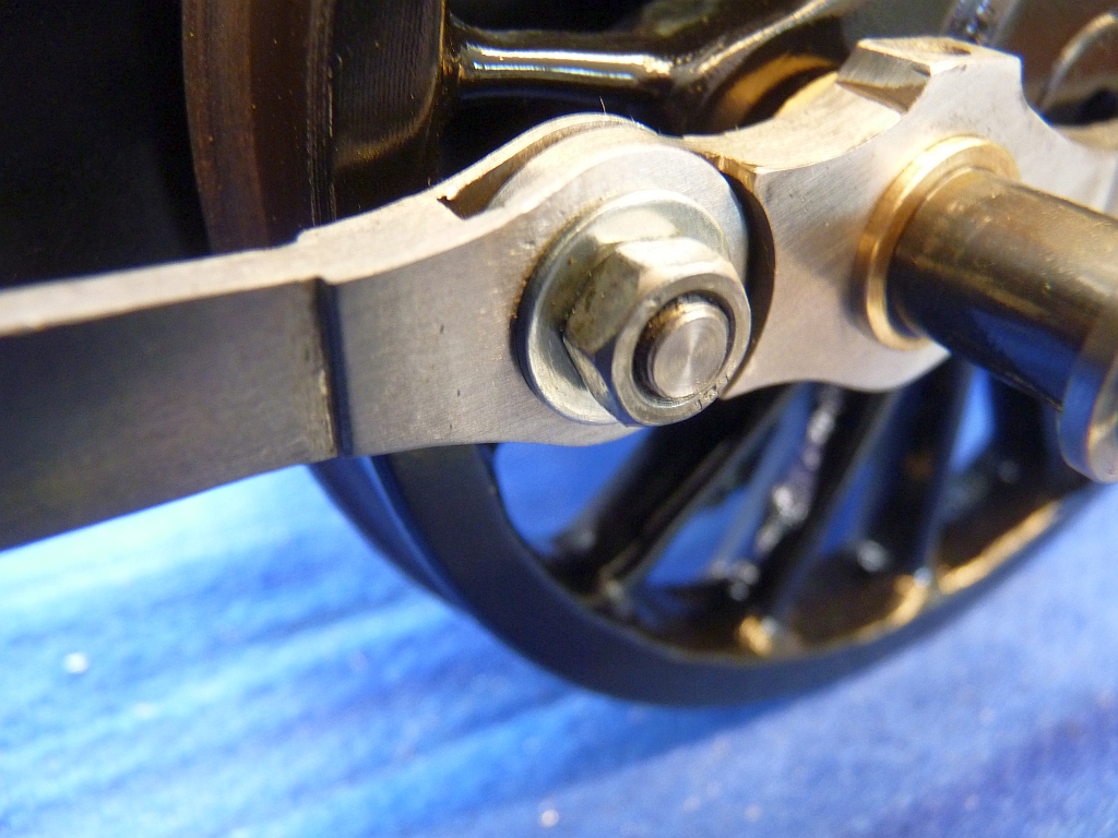
The rods are still far from perfect but they are much better than they were. I replaced all the crankpin bushes with new ones machined from leaded bronze bar. The originals were brass I think and a very sloppy fit. Time to see if the rods fitted and I was expecting problems here, especially as I had remachined the knuckle joints, and I had visions of having to make some eccentric bushes to get them to fit on the crankpins. I was amazed when the rods fitted quite well with only a couple of tight spots. All the bushes had been reamed to 10mm diameter to suit the crankpins and there was no play in them at all. I just eased the front and rear bushes slightly but left the driving crankpin ones as finished and the tight spots have now gone. Big sigh of relief!
The coupling rods are retained by collars with split pins through them on the driving and trailing axle and a top hat shaped washer with a countersink screw for the front crankpin.
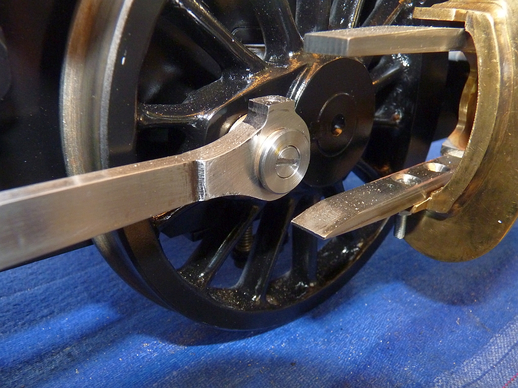
I replaced all the collars with new ones and then I realised that I hadn't drilled the split pin holes in the ends of the new crankpins! Good job I hadn't finally fitted the eccentric straps on the driving axle as I had to remove it again to put the wheels on the mill to drill the holes. The trailing axle got the same treatment. Both axles were refitted to the frames and the eccentric straps refitted, this time with threadlock on the nuts. Hopefully the straps won't have to come off again!
When I was redesigning the valve gear I noticed that another improvement in the valve events could be made by shortening the lifting arms on the weighshaft by approximately 0.3" so I decided to do this. The new holes for the attachment of the lifting links were far enough away from the originals not to cause any problems. The new holes were drilled and reamed and then the arms reprofiled to suit. Actually, the arms are one block rather than separate which looks a bit ugly but I wasn't going to remake them.
The bore in the block was a very sloppy fit on the weighshaft so I bored it out and fitted a brass bush to bring it back to size. The weighshaft itself was a bit undersized as well so I replaced it with a length of silver steel.
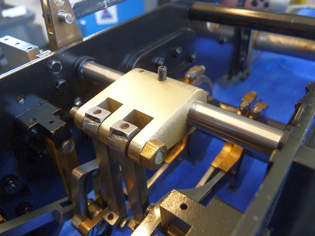
Because I had shortened the lifting arms I had to shorten the reversing arm on the weighshaft as well to suit, otherwise the reverser would have needed more travel to move from full forward to full reverse gear. Fortunately, again, the new hole for the attachment of the reach rod was far enough away from the original to avoid problems. The problem I did have was that the replacement running board bracket I had fitted earlier prevented the reversing arm going far enough forward so I had to cut a slot in it to clear the arm. On the original Praire, this bracket is actually the mounting for the crosshead pump which is not fitted on this loco (although I think it's in the box of bits somewhere) and that may not foul the reversing arm like my new bracket does.
A few photos of the chassis and valve gear so far:
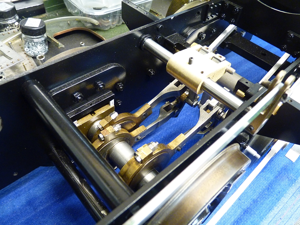
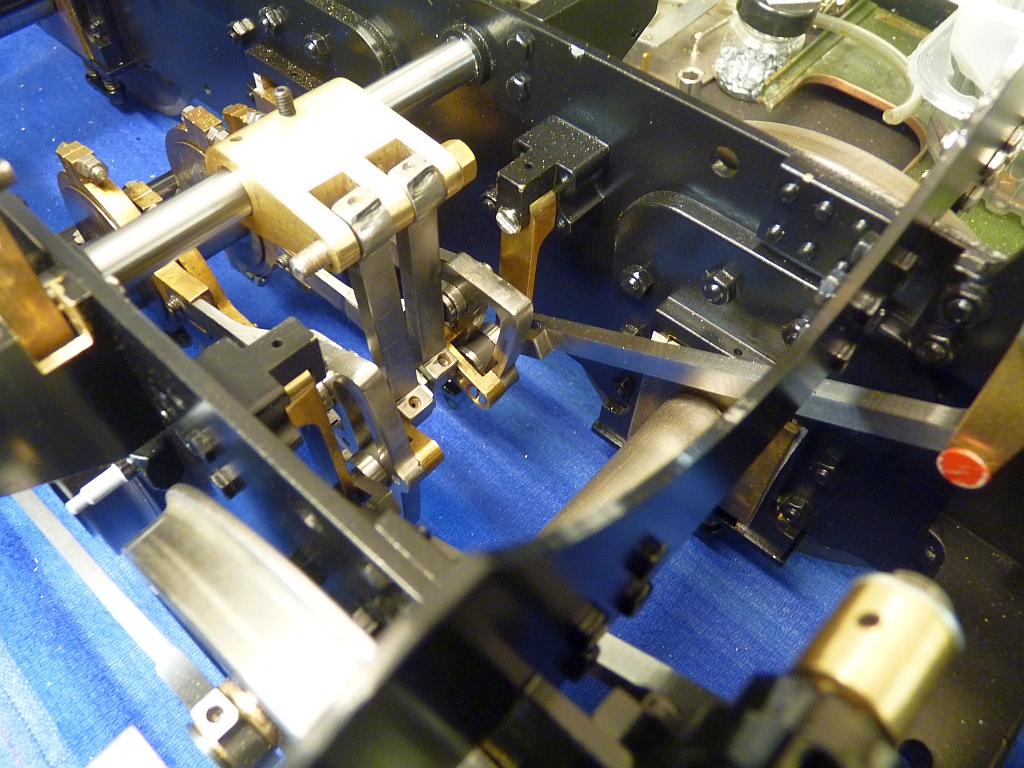
Photo of the reversing arm showing the new attachment point for the reach rod. It still needs reprofiling here. You can see the slot that I had to cut in the running board bracket to allow the arm to go far enough forward.
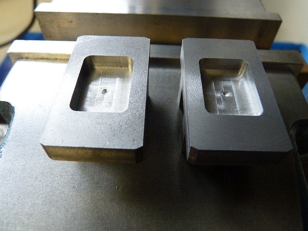
The next job tackled was making the new valves. These were machined from slices of 50mm round cast iron bar. The bar was held in the 3 jaw in the lathe and faced both sides to thickness. They were then milled to a rectangular shape, the length being left oversize to allow for final finishing to size after the exhaust cavity had been machined. This continuous cast bar is lovely stuff to machine but very messy! It cuts like butter with carbide endmills.
Once I had the basic rectangular shape, the top of the valves were milled to shape with the central slot for the driving nut and then the valves turned over and the exhaust cavity milled out.
I'm always very nervous when I'm machining the exhaust cavity in a valve. It's very easy to turn the feed handle the wrong way if you don't concentrate and take a piece out of the edge! Fortunately, these valves came out fine.
I'm seriously considering getting a set of DROs for the mill as it would make it so much easier for doing jobs like this.
Last job on the valves was to trim the length to give the correct valve lap.
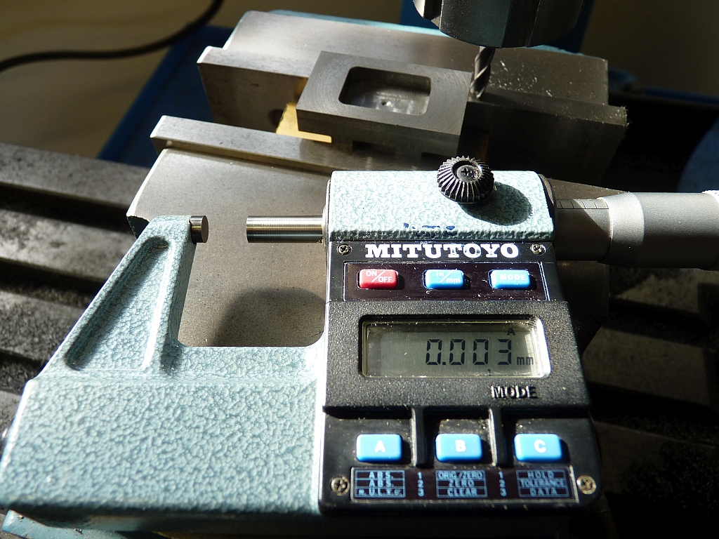
A few weeks ago a friend at the club gave me a Mitutoyo digital micrometer so I used it for the first time to measure the width of the lands. It's quite an early model and so is a bit big and chunky but it works perfectly. The accuracy is much better than my machining ability!
02/04/2016
Just a final update on this project. I've been so busy with other stuff that I haven't had time to document anymore of the rebuild. I've described most of the interesting stuff anyway. The rest was just platework and the tender. It's now gone back to the chap I was rebuilding it for who wanted it back before I had managed to completely finish it. There wasn't much left to do - just a bit of pipework and a few small jobs and he was going to finish those off himself. Frankly, I'm glad to see the back of it! If I'd realised that it was going to be such a lot of work I would never have taken it on.
Other jobs completed included a new tender virtually built from scratch. I only managed to use the original wheels, the dummy springs, the buffers, and the brake blocks. Everything else went in the scrap bin as it was utter crap! I can't believe how poor the workmanship on the original tender was. The new tender tank was a laser cut kit from Model Engineers Laser held together by slots and tabs and just soft soldered together. I did have problems with the brass top decking distorting due to the heat of the soldering as there was nothing to support the edges at the sides. If I were to build another one, I would use some brass angle on the edges to hold everything straight and flat.
I had to rebuild the cab for the loco as the original didn't fit anything like properly and I had to make a new spectacle plate for it and new valances. Whilst doing that I found out that the firebox on the boiler wasn't in line with the barrel. It was at an angle which meant that the firebox is at an angle to the frames. Also, the mounting blocks on the sides of the firebox that sit on the frames were at different heights so the backhead leaned over at an angle! I managed to get it something like right after a bit of fiddling and putting some packing under one of the blocks.
The rear running boards were scrap so were replaced with new ones. I didn't bother refitting the dummy splashers as they were also scrap. It would have been difficult to fit the right hand ones anyway as the reach rod for the reverser was in the way.
I fitted a new mechanical lubricator bought as a kit from Steam Fittings rather than try and refit the strange hydrostatic system fitted originally.
I did manage to run the chassis on air before it went back and it actually ran very well indeed, ticking over nicely on 10 psi so I must have got the new valve gear right.
I never got around to taking any photos of the finished loco but it doesn't look too bad now. Just hope it runs ok. I would have prefered to give it a test run before it went back but I just ran out of time.