2
14/02/2010
After reboring the second casting to the same bore as the first one, the castings were then bored for the valve liners. A larger piece of packing was used under the block to raise the centre of the liner bore to the right height and the cross-slide wound across to move the casting by the distance between the centrelines of the bore and the liner. Both castings were done with no problems this time.
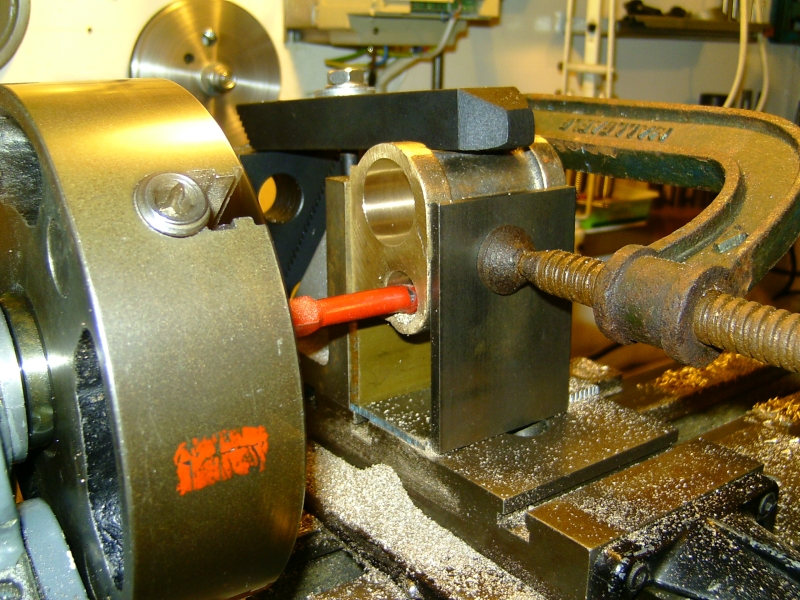
Boring for the valve liners
The next job was to face off the ends of the castings. It is critical that the rear face that takes the rear cylinder cover is perfectly square to the bore in order that the piston etc.will run smoothly without binding at any point. The face for the front cover is not particularly important as that is just a plain disc with no glands and serves no purpose but to blank off the end of the bore. This would not be the case however if the front cover carried a long boss to support an extended piston rod as fitted to some locos.
The easiest way is to face off the rear of the casting at the same setting as when the cylinder bore is machined. I could have done one of the castings like that but not the other using the setup that I did. To use this method for the other casting I would have had to reposition the angle plate etc. so that the correct end of the casting was facing the chuck i.e. the angle plate would have had to have been moved to the front of the cross-slide instead of at the rear. It took enough time to get the thing set up in the first place and I didn't want to have to do it again!
The other way of facing the castings is to machine a mandrel held in the chuck on which the castings are fitted and then faced off. The mandrel needs to be just the right size so that the castings can be pushed on and held with sufficient grip to take the cutting forces. The various writers recomend using brass for the mandrel but I didn't have any of a suitable size so used a length of alloy bar that was lying around - big mistake I think!
The bar was machined to diameter such that the casting would just push on reasonably tightly. When doing this use both bores as a gauge as one may be slightly bigger and you need to initially machine the mandrel to suit the larger bore (obviously).
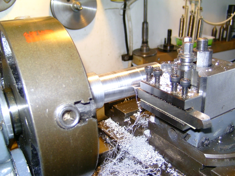
Finish machining the mandrel
The first casting was pushed onto the mandrel and seized solid when it was nearly all the way on! I couldn't move it one way or the other. I think the alloy had 'picked up' on the bore and stuck solid. I think I should have put a bit of oil on the mandrel before fitting the casting to stop this happening. By now, I was beginning to think that the whole job was cursed!
Anyway, I went ahead and faced the first end of the casting with no problems but how to get the casting off the mandrel with doing too much damage. I marked the mandrel so that it could be returned to the chuck in the same position and took it out the chuck. I then tapped the mandrel out of the casting and when it had gone so far, it came out quite easily. Fearing the worst I inspected the bore but fortunately there was only a shallow score right at the end of the bore where it will do no harm. Very annoying though!
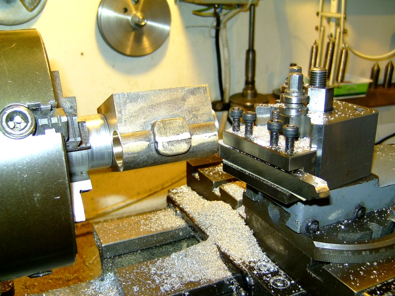
facing the ends of the casting
The mandrel was returned to the chuck, checked for true running and the mandrel cleaned up with a fine file and some fine emery paper. This time I put a spot of oil on the mandrel and as it was now slightly loose in the bores, I fitted the castings with a strip of kitchen foil between the mandrel and the casting. This took up the 'slack' and made the castings a nice fit. The remaining faces of the castings were then machined with no problems. Were I to use this method again, I think I would make up a split mandrel that could be expanded with a bolt so that the castings were a sliding fit and then gripped by tightening the bolt. Much safer!
There was quite a bit to take off to bring the castings to length so I made sure that an equal amount was taken off each end to keep everything central.
The castings have a boss on the top of the valve chest to take the steam pipe and this needs to be machined at 30° to the bolting face. I decided the easiest way to machine this was to hold the casting in the machine vice on the mill and tilt it at the required angle. The angle was measured using an ordinary plastic set square as I don't think half a degree here and there will make any difference in this situation. I'm not one for wasting time on precision when it's not needed!

Milling the boss for the steam pipe
I used some kitchen foil again here to protect the casting from marks. I must see if there is a thicker version available as it's ideal for this.
You'll notice that a large chunk of the boss remains unmachined. This is because the steam pipes on Doris actually bolt on vertically instead of at an angle. I wonder if the castings that Reeves sell are the same or if they have altered the design to suit the S15?
18/02/10
The last major machining operation on the cylinder castings is drilling the steam passages from the valve chest to the ends of the cylinders. These are 9/32" long by 1/8" wide and are angled at about 30° to the bores. Another awkward operation as the castings need to be held at two angles; one to get the passages lined up with the centreline between the valve chest and the cylinder bore; and the second to get the passages at the 30° angle.
More head scratching and I eventually bolted the castings to the vertical slide with the bolting face set with a cardboard template to get one of the angles and the vertical slide rotated on the cross-slide to get the 30°.
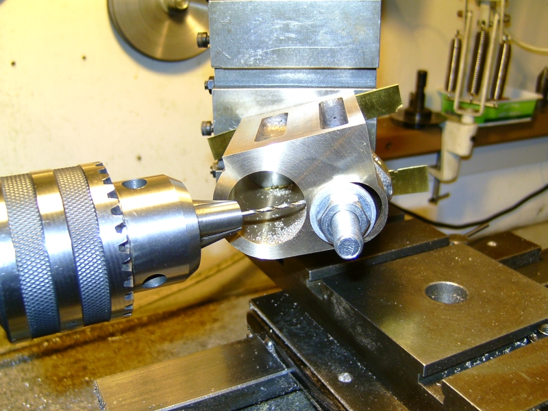
Drilling the steam passages
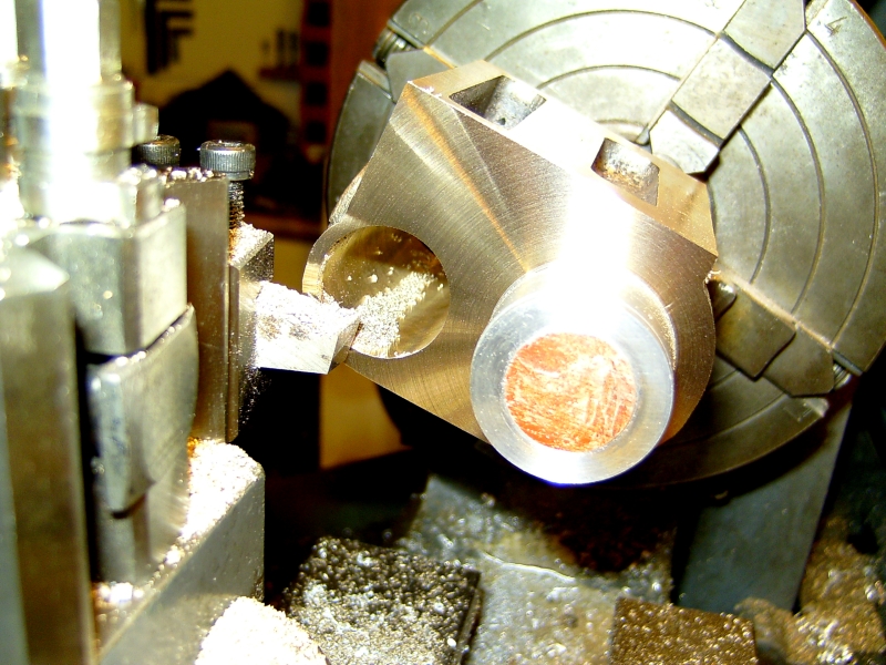
The ports were cut by drilling two 1/8" diameter holes at each end and then the centre part removed with a 1/8" endmill. Before drilling, a flat was machined inside the bore with the endmill to give a flat surface for the drilling operation. Obviously if you tried to drill into the bore at an angle without the flat, the drill would wander all over the place. Martin does say to file a flat on the end of the bore before drilling but I prefer to have the ends of the passages just inside the end of the bore so that the gasket face for the end cover is not reduced at this point leading to possible leakage under pressure.
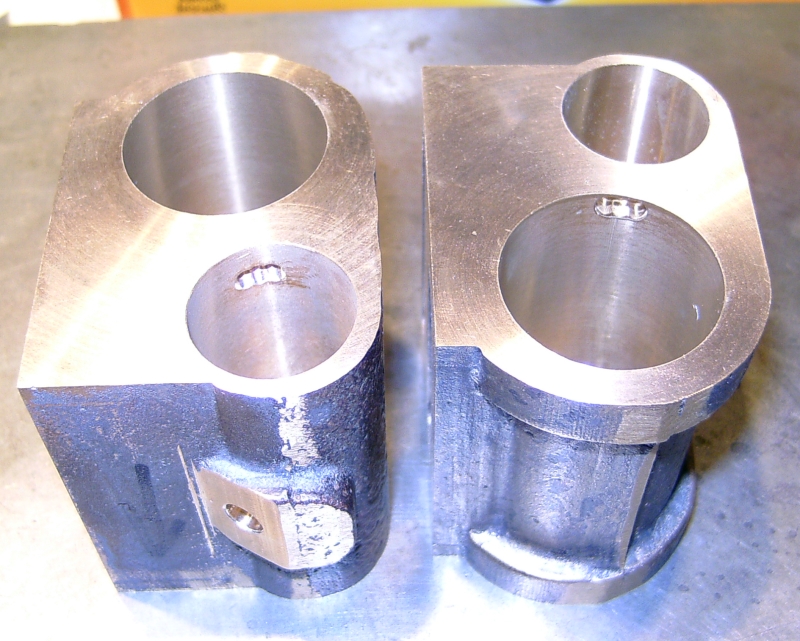
Passages drilled - just need a touch with a file to clean up
I'm now waiting for the materials for the end covers and the valve chest liners so no more will be done until they arrive.