,,,,
Kennet
2
15/12/2007
The next item on the agenda is the quill that fits in the column head and in which the spindle for the grinding wheels runs in two ball races. The races are designed to have a certain preload which is applied by four dished washers acting as a spring and pressing on one of the bearings.
The machining of all the items for the quill and spindle etc. involves some serious swarf making and it's jobs like these that make you realise how much metal you waste!
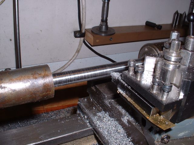
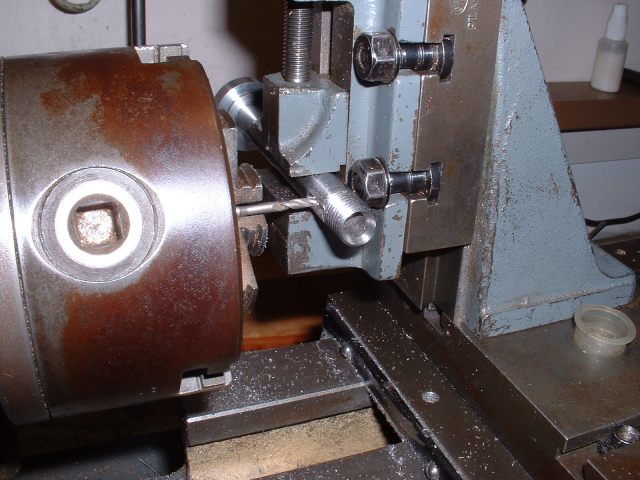
The quill is machined from a length of 1½" dia. mild steel bar which requires turning down to 1-3/8" dia. and then boring out to take the bearings and the spindle. The length of bar was held at one end in the 3 jaw chuck and the other supported in the fixed steady. The end was then faced and deeply centred so that the steady could be removed and the end of the bar held in the rotating centre. The required length was then turned down and parted off after re-fitting the fixed steady to support the bar near the point of parting off.
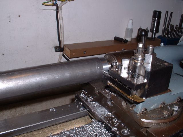
Turning down the outside diameter of the bar
Parting off the required length for the quill
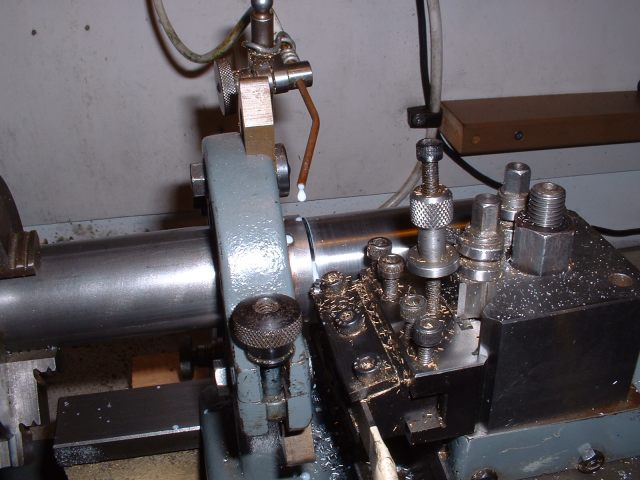
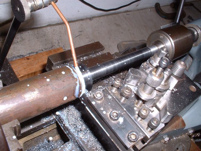
The embryo quill was then held in the 3 jaw again with the other end supported with the fixed steady. It was then drilled through 1/2" dia.(my largest drill!) and finally bored out to 1-1/6" internal diameter. It would have been a lot easier to start with a piece of thick wall tube! The final boring job was to open out each end to accept the two ball races.
Turning the bar into a tube!
Boring each end for the ball races
Last job on the quill was to drill and tap 2BA a hole on the top centre of the tube for oiling the spindle bearings.
The spindle also involves turning down a length of bar and this was done as before. The end of the spindle requires a thread machining on it to take the pulley securing nut and this was done prior to parting the spindle from the bar stock. The plans call for the thread to be ½" x 32tpi but as I didn't have a tap and die of that size I used ½" BSF instead. Much coarser but I didn't see a problem with that apart from the fact that the larger threads are more difficult to cut with a die. To help here I decided to screw cut the thread roughly first and then finish it with the die. I can't remember when I last screw cut a thread - must be over 20 years ago!
Turning down the spindle
Parting off
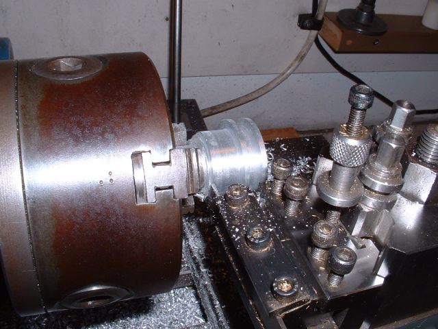
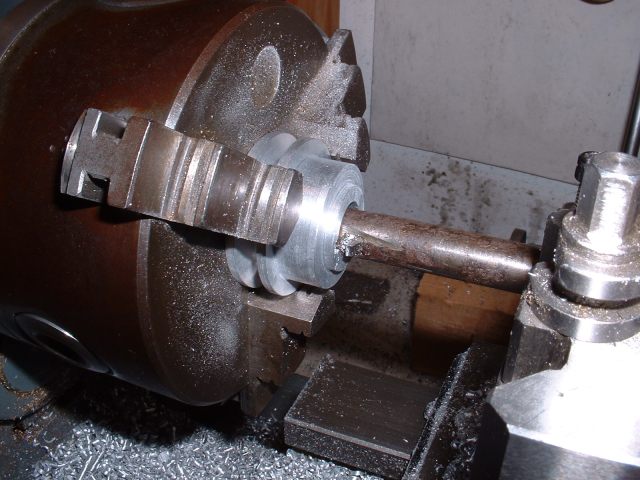
The larger end of the spindle has the centre hole reamed 5/16" diameter and then countersunk to a diameter of 5/8". This is to accept the sub-spindles that each grinding wheel is mounted on. The sub spindles have a short spigot that fits into the reamed hole in the main spindle and a tapered part that matches the countersink in the main spindle. The sub-spindles are locked in place with a drawbar through the main spindle. The idea of this is that each wheel will always run true when fitted to the main spindle and will not require dressing every time the wheel is changed.
The countersink is a standard 60° and could be made with a centre drill if you have one of big enough diameter but of course I hadn't! Instead I used the biggest centre drill I did have (½") and then bored it to finished size by setting over the top-slide to the required angle.
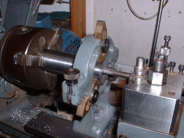
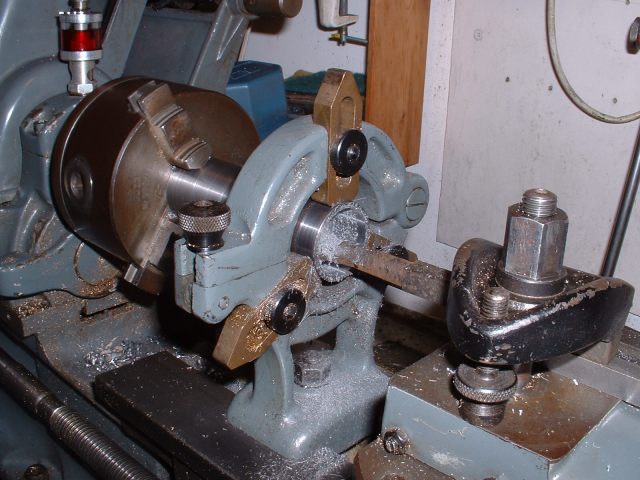
Of course, the reamed hole and the countersink must run truly with the spindle so care must be taken that the spindle runs truly when held in the chuck. I used a dial gauge to check this. Fortunately the original chuck is still pretty accurate despite years of use (and abuse!) but I have to tighten the jaws using a certain key hole to get this accuracy. The hole to use depends on the diameter of the work held so it's a case of trying all three to find the right one! Apparently most chucks centre better using a certain key hole and sometimes this is marked on the chuck. The only problem with this chuck is that the jaws have worn slightly bell mouthed due to holding work at the end of the jaws (a very common fault) but it holds long bars perfectly. Incidently, I recently bought a new 3 jaw to replace this old one and the accuracy of the new one is nowhere near as good as the old one!
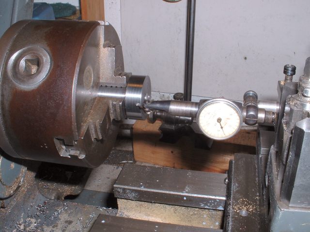
Using a dial gauge to check the spindle is running true
Boring the countersink to required diameter
The final job on the spindle was to cut a keyway in the end for a 1/8" square key to secure the driving pulley. This was done with a 1/8" slotdrill in the vertical slide.
Cutting the keyway for the pulley
The driving pulley is machined from an aluminium casting and I hate machining aluminium. It is very difficult to get a good finish due to the chips welding themselves to the tip of the tool, especially if heavy cuts are taken.
The casting has a generous spigot for holding it for turning. This had been ground fairly round so I held this in the chuck, got it to run as truly as I could and then skimmed the outside of the main casting to get it circular. I then reversed the casting in the chuck and turned the chucking spigot true. The casting was reversed again to complete the machining of the pulley. I had intended to turn the pulley with the boss outwards which would have been easier but the casting had some very bad blow holes which would have intruded into the pulley part so I had to machine it the other way around. Not that much more difficult really but makes machining the boss a little more awkward.
The groove for the round belt is V shaped with an angle of 40° and sorting through my pile of lathe tools revealed one with a suitable angle ground on the end! This was plunged straight in as far as possible before chatter set in and then moved sideways to widen the groove and give clearance. It was then plunged in again and the process repeated until the groove was the right width and depth. The pulley was then drilled and bored out to a good fit on the spindle, finally parting it off to the right length.
Parting off the machined pulley
The pulley now needed a keyway cutting and this was done in the lathe using a square tool in a boring bar mounted in the toolpost. The keyway was cut by moving the tool back and forth through the pulley bore using the saddle feed and the tool advanced a few thou at a time. I used this method for cutting the keyways in the gears for the bending rolls.
Cutting the keyway in the pulley bore
The last two items for the spindle assembly are a tubular spacer to fit between the ball races and a nut to hold the pulley onto the spindle. The spacer was a simple turning job from steel bar but it's actual length has to be finalised when the spindle is assembled as it's length determines the pre-load on the bearings.
The nut is also a simple turning job from bar with two spanner flats milled on the sides. I started tapping the hole in the nut in the lathe using a tap in the tailstock chuck but the force needed to tap the thread caused either the tap to turn in the chuck or the work to turn in the lathe chuck. To make it easier I machined the flats on the nut first and then gripped it in the vice and finished the thread using the tap in a tap wrench. No problem then.
All I've got to do now is put all the bits together and machine the bearing spacer to correct length to give the right pre-load on the bearings. The spacer should be of such a length so as to cause the 4 disc springs to be compressed by about 20 thou.
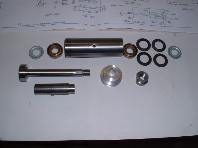
The components for the spindle assembly ready to be put together
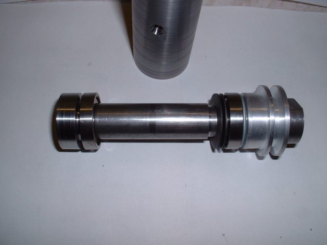
Spindle loosely assembled to show where all the bits go!
16/12/2007
This morning I assembled the spindle and quill. The only problem turned out to be that the spacer I made that goes between the bearings was slightly too short and caused the spring washers to be compressed too much. Rather than make a new one I found a suitable washer to make up the length!
I noticed that when the pulley nut was tightened up, the spindle, although rotating smoothly, seemed a little tight. I thought that the pulley was catching on the inside of the quill but it turned out to be the Nilos bearing seals. These are thin metal seals to protect the bearing from the ingress of dirt etc. They rotate with the spindle and have a turned over lip that bears on the outer race of the bearing so the 'stiffness' was caused by the friction of the seal rotating against the race. I presume this is supposed to happen.
I next tackled the motor pulley which is another pretty simple turning job. This large pulley is another aluminium casting but seemed to machine a little better than the spindle pulley and didn't have any serious blow holes in it fortunately as there is not a lot of surplus metal to machine off. There are actually two different sized pulleys available depending on the speed of the motor used i.e. 1440 rpm or 2880 rpm. My motor was 1440 rpm so I needed the larger of the two.
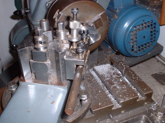
The rough casting was held in the 4 jaw this time due to it's size. This allowed the boss to be machined and the inside face of the pulley. The 4 jaw was then replaced with the 3 jaw and the casting held using the machined boss. The outer face of the pulley could then be machined along with the edge and the groove for the belt. Finally the bore was drilled and reamed to suit the spindle of the motor and the boss of the pulley drilled and tapped for a securing screw.
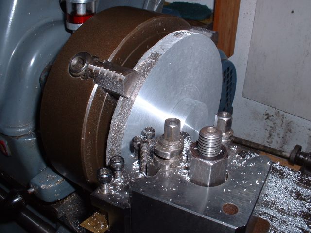
Turning the boss and one side in the 4 jaw
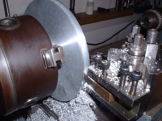
Turning the groove after moving to the 3 jaw
<Previous Page.......Next Page>