Allchin Traction Engine Cylinder and Other Bits
Page 2
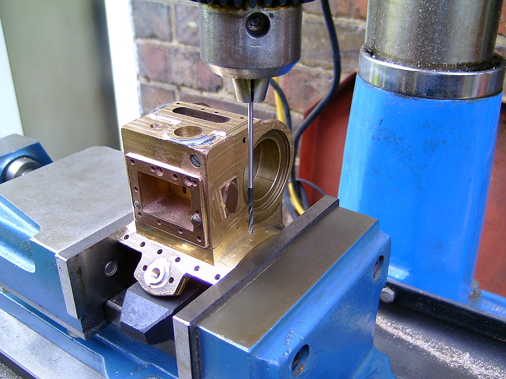
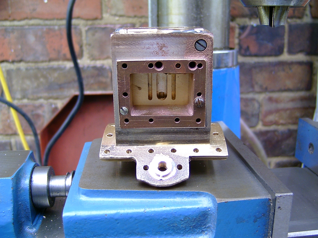
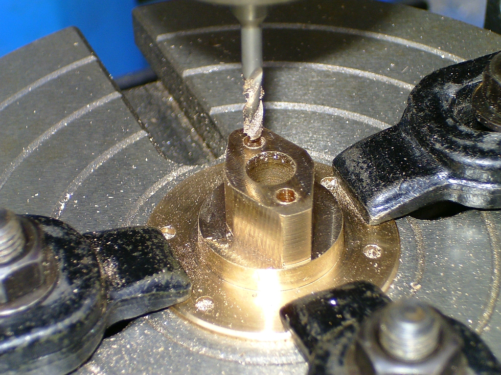
Next I tackled the drilling of the mounting holes for the cylinder to the boiler. These were marked out on the flange and then centre popped. I used a long pointed rod to line the centre pops up with the mill spindle and rotated the cylinder casting in the vice so that the holes were perpendicular to the surface of the flange.
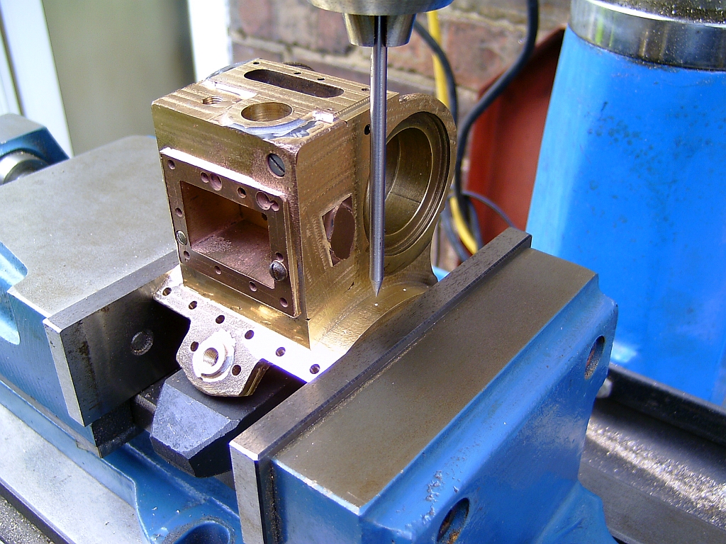
The holes were then drilled one by one using a long drill bit.
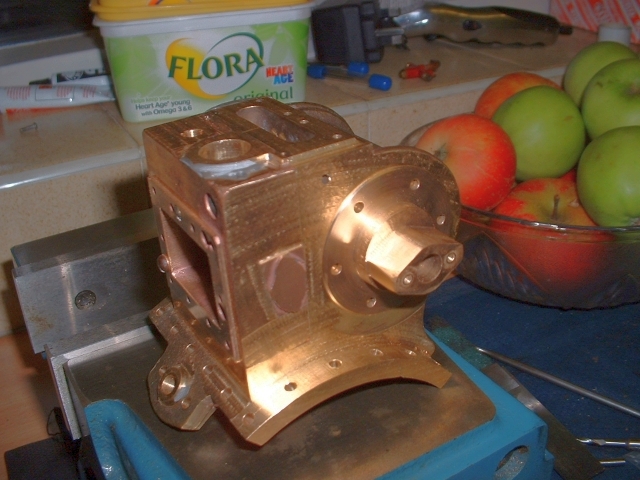
All mounting holes drilled. More JB Weld used to repair the boss for the governor.
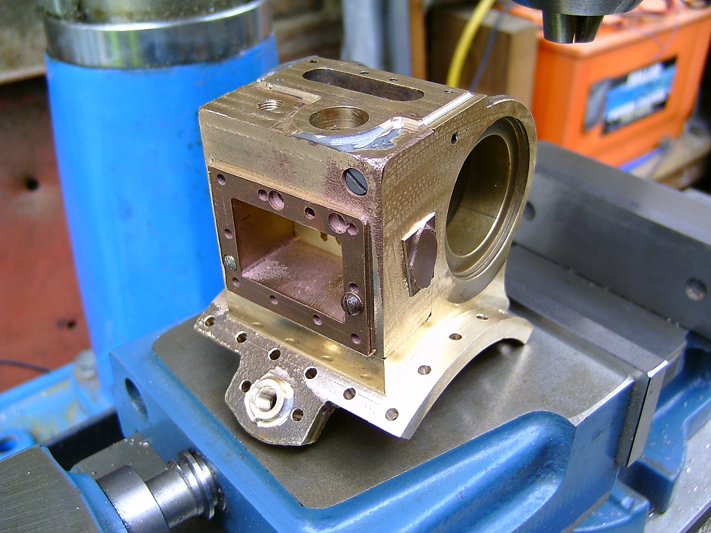
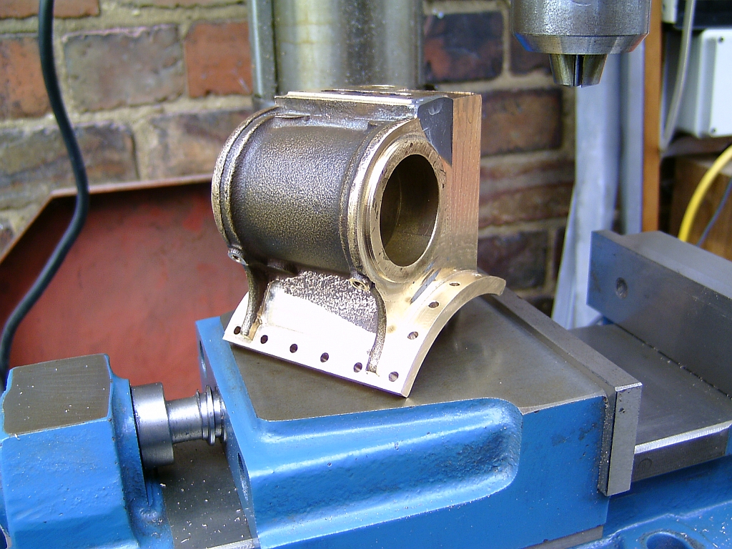
At some point before this I had machined the washout plug boss on the cylinder mounting flange. I think I did it by mounting the casting on the rotary table with the boss centred on the table and machining the boss with a ball ended end mill. As mentioned before, some of the details are a bit vague after all this time!
Next to be tackled were the front and rear cylinder covers. I must have already machined and fitted the cylinder liner at this point. That was just a fairly simple turning and boring job with the liner being secured into the cylinder casting with Loctite.
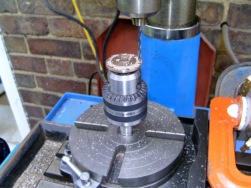
The front cover was a simple turning job with a threaded boss on the outside to secure the steel cylinder end cover. The bolt holes were drilled using the rotary table.
The cover was turned from mild steel bar and polished. It's secured to the cylinder end cover with a stud and a nut. I must have made the valve chest cover at this time as well and made and fitted the proper bolts for securing the valve chest to the cylinder casting and finally fitted the valve chest with Loctite at this point. I think I machined some special bolts from phosphor bronze for this.
In full size, the cylinder and valve chest would have been one casting but making them separate like this makes the machining a lot easier.
I think that the rear cylinder cover had already been machined but was a bit rough so I cleaned it up. I certainly cleaned up the outside of the boss and the bore for the gland nut.
I seem to recall that the threaded holes for the gland securing bolts had been drilled and tapped but a bit skew so I adjusted their position with a 1/8" endmill, Loctited in a bit of brass bar and then redrilled and tapped them.
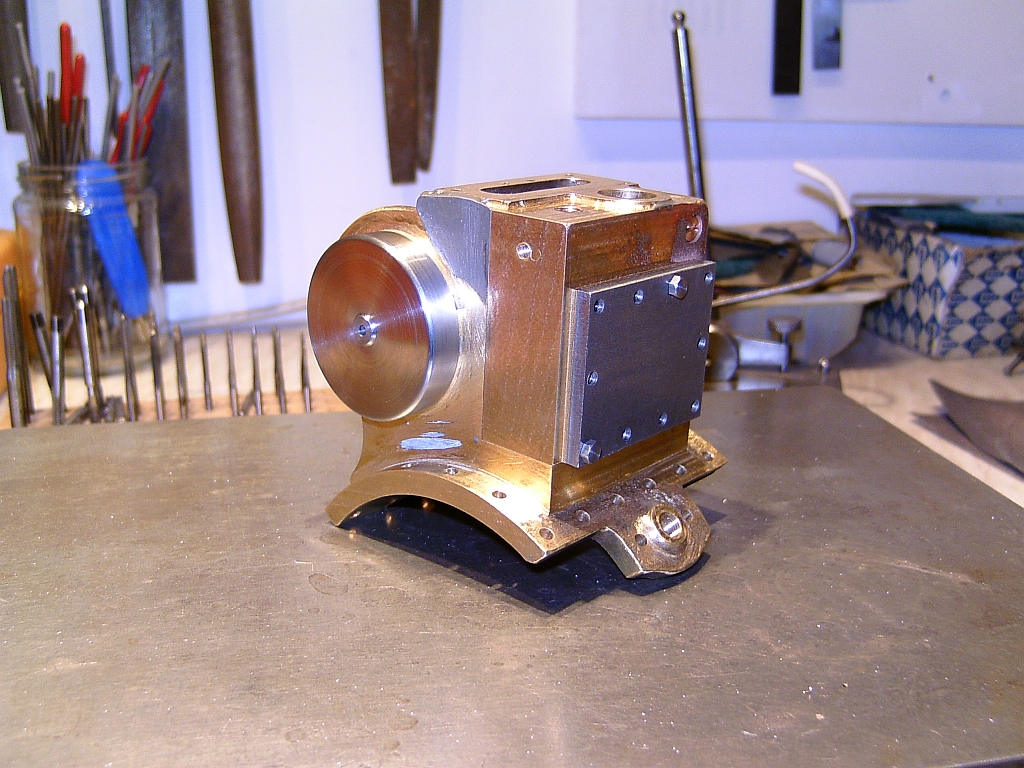
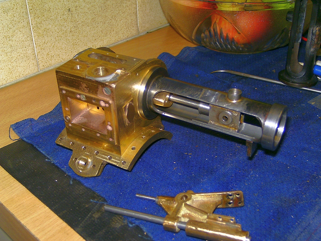
Rear cylinder cover on the cylinder block:
Onto the trunk guide. This had been completely botched and a bit beyond repair. The/A previous builder had fitted the motion bracket to the wrong side of the trunk guide so the mounting faces on the trunk guide were on the wrong side as well. Gary's friend had tried welding up the trunk guide to repair it but the heat from the welding had badly distorted the casting. It had already been partly machined and bored for the crosshead prior to the welding and I considered it basically scrap and beyond repair.
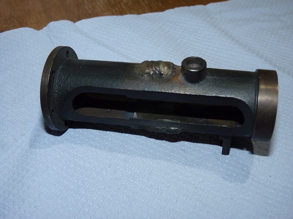
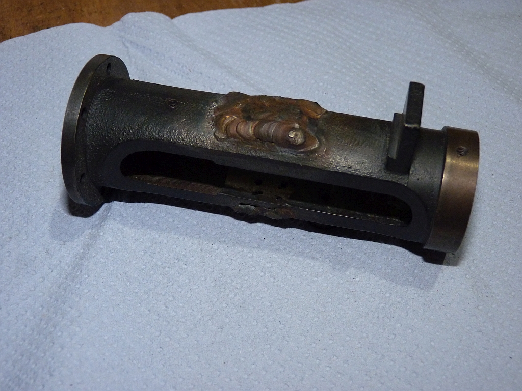
Rather than buy a new casting I decided to fabricate one from scratch using steel bar.
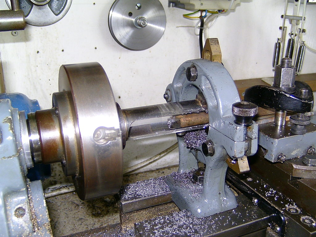
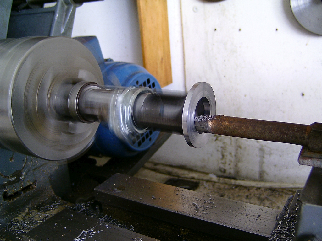
I had a length of suitably sized steel bar to make the main part of the trunk guide so this was set up in the 4 jaw chuck to run true and then supported with the fixed steady. The outside was turned to diameter and the centre bored out leaving some allowance for final machining in case the whole thing distorted when it was all silver soldered together.
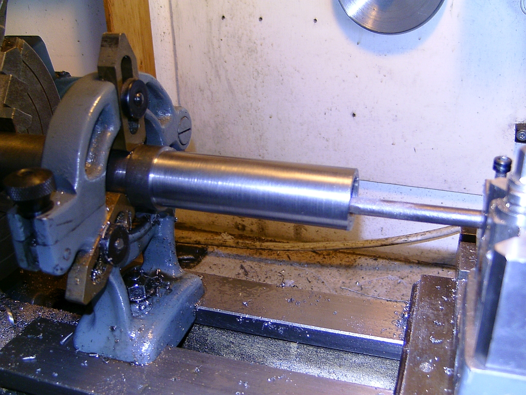
The bar wasn't big enough to include the flange that mounts the guide to the cylinder so this was made as a separate piece. I think it was cut from a piece of flat bar and then machined to size.
The flange was then silver soldered to the main barrel of the guide.
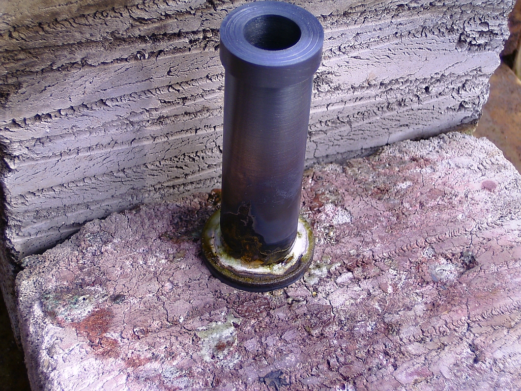
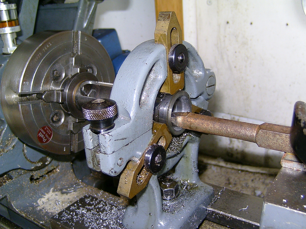
After cleaning up the assembly was mounted in the 4 jaw again with the end supported by a live centre in the tailstock. The inside of the flange was given a light skim so that it ran true to the barrel.
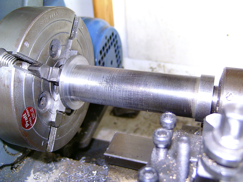
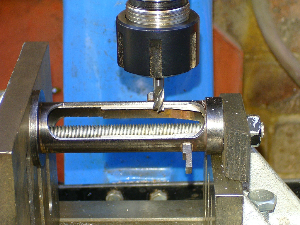
The assembly was mounted between two angle plates on the mill table and the outside milled to shape with a large (22mm?) endmill.
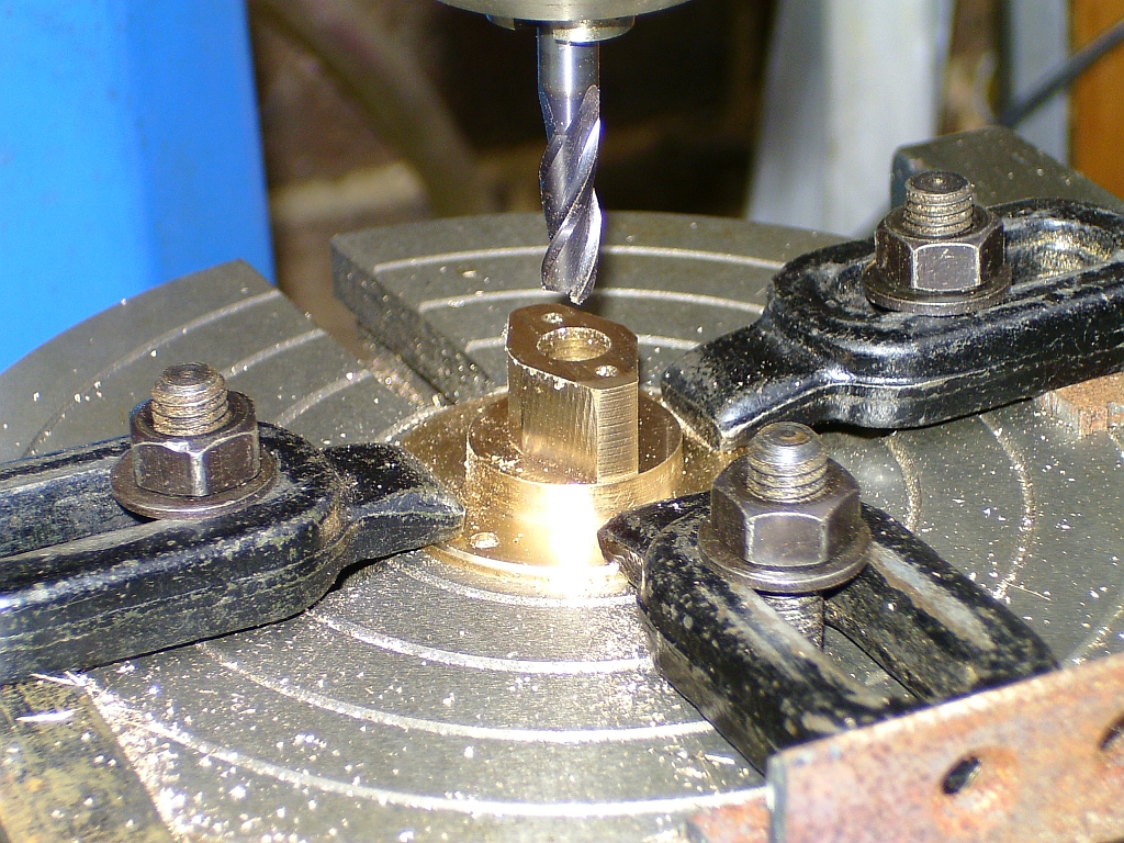
The oil pot and the mounting lug were machined and silver soldered in place.
The inside edges of the slot in the sides of the trunk guide were then machined to the correct profile with various endmills. The shape of these edges is quite complicated and requires various positions of the guide to get the surfaces at the correct angles.
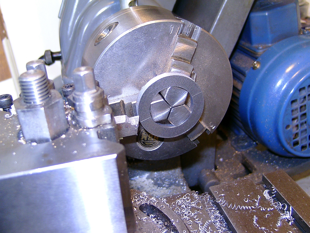
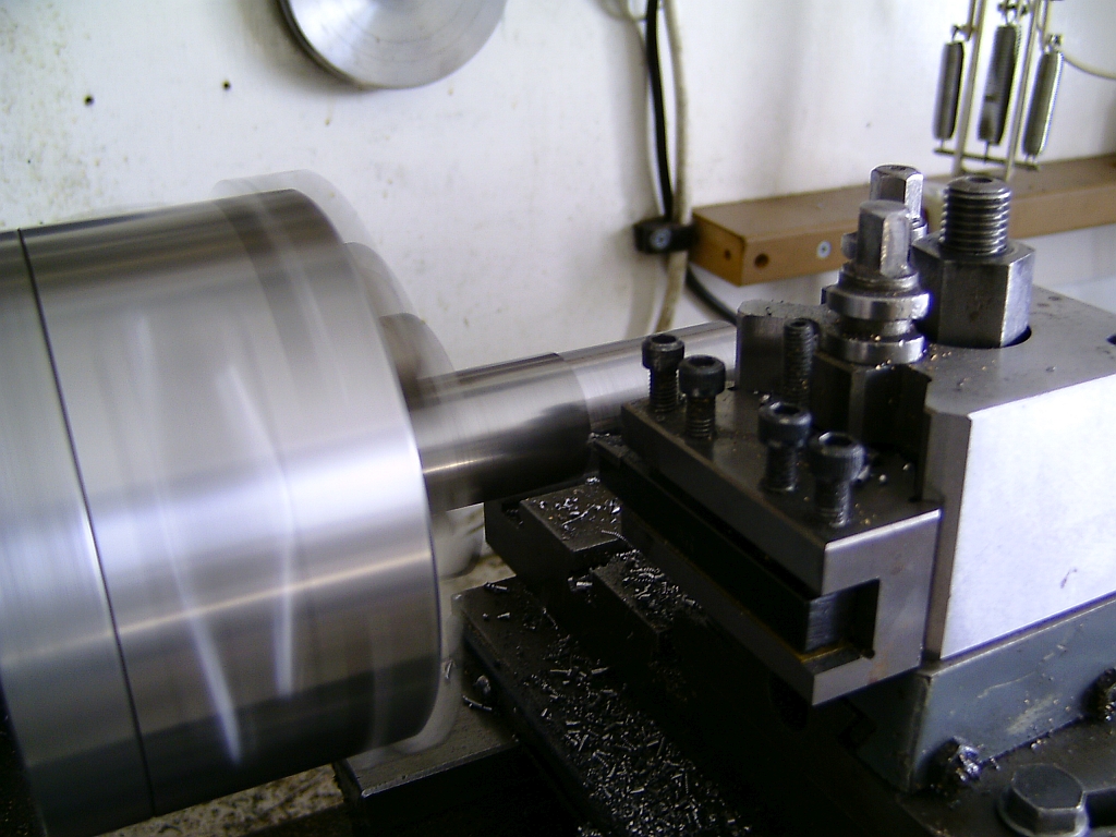
Finally, the guide was mounted in the lathe again so that the bore could be finished to size.
A mandrel was machined in the 3 jaw chuck to a good fit in the bore of the guide and the guide mounted on that for machining the bolting face of the mounting flange and boring out the larger end of the bore to fit the spigot on the rear cylinder cover.
It was all quite a long winded job but very satisfying to see the end result. I honestly can't remember whether I used the original crosshead and piston or made new ones. I had also machined the flats to take the motion bracket at this point.
< Previous Page .........Next Page >