Allchin Traction Engine Cylinder and Other Bits
Page 3
The motion bracket is a separate casting that is held to the trunk guide by countersink head screws.
The bore for the valve rod had been drilled/reamed out of square with the bracket so I drilled it out, fitted a bronze plug and then redrilled and reamed it correctly.
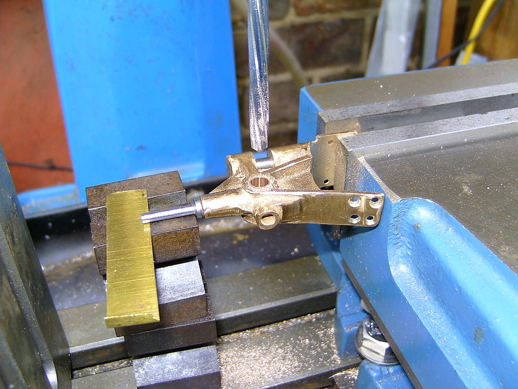
To line up the motion bracket before drilling and tapping the holes for the screws in the crosshead guide I made a sort of jig to line up the bore in the motion bracket with the trunk guide. This is shown on the drawings so I just followed that. The motion bracket was then secured into place.
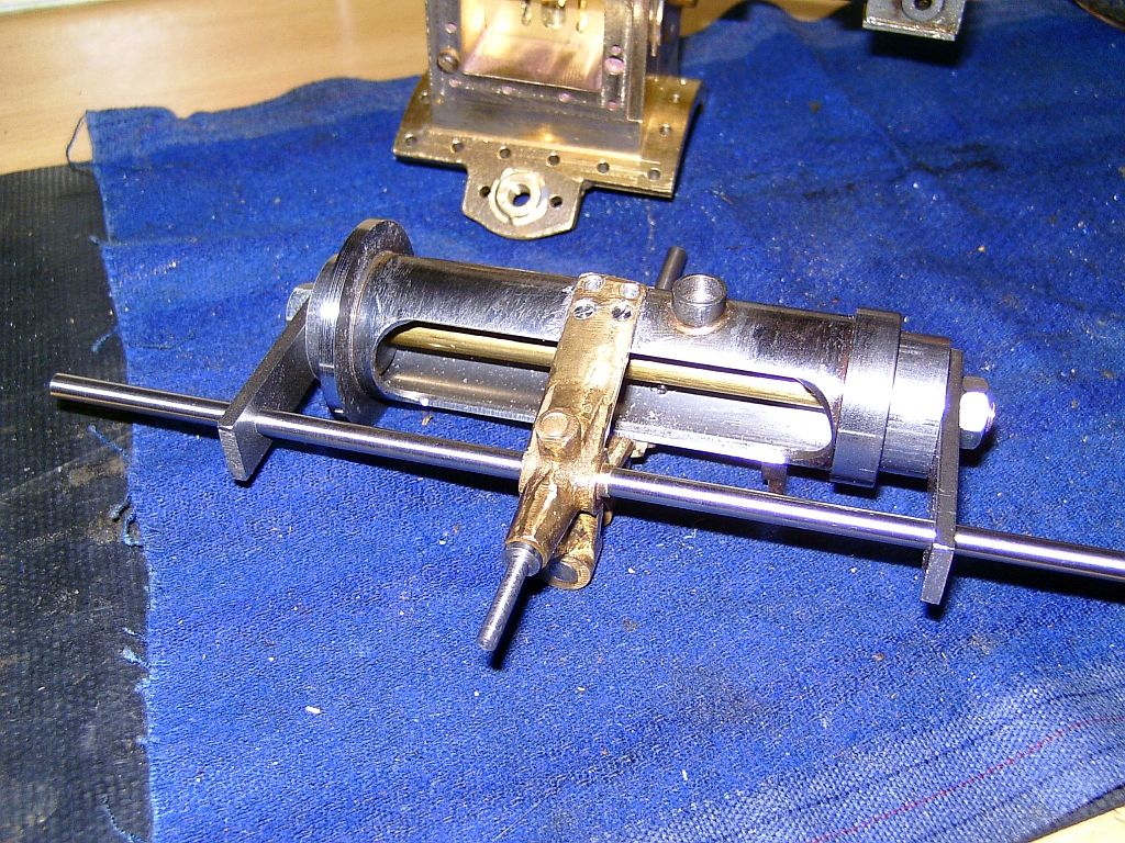
The join was filled with JB Weld
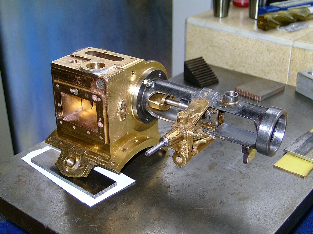
I don't seem to have any more photos of this but the joints were filed flush and cleaned up so that the trunk guide and motion bracket would look like one piece when it was painted.
I worked on the safety valve casting next but decided it was too badly machined so scrapped it. It wasn't a very good casting anyway. Instead I completely fabricated a new 'casting' from scratch. Unfortunately, I don't seem to have any photos of that either.
Various other parts were made or finished including the slide valve and valve rod and the regulator, but again, no photos.
The last major item was the governor assembly and I have to say that this was probably the most tedious and fiddly job I have ever done!
The main governor casting had been machined but the bottom spigot that fits into the steam chest and holds the steam valve was very poorly done. I ended up turning it down and silver soldering a sleeve on it and then turning to size again.
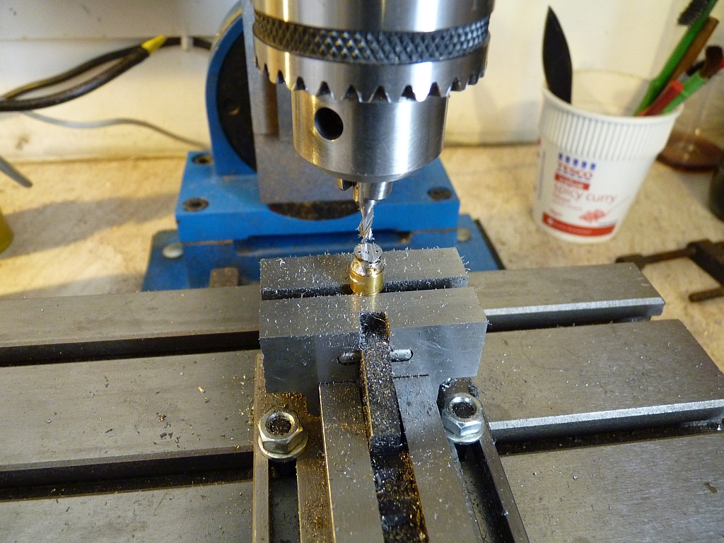
I did have the bevel gears for the drive but had to make everything else from scratch. The worst bit was making the round ball weights for the operating mechanism. They are made in two halves screwed together either side of the vertical springs and I machined the halves from mild steel bar using a form tool. The halves then had to be drilled for a stud to screw then together and one half drilled to take the little wire loop that stops the balls flying out too far.
I found the easiest way to do this was to soft solder the halves of the ball to a bit of brass rod. This could then be held in the lathe chuck and the mill vice.
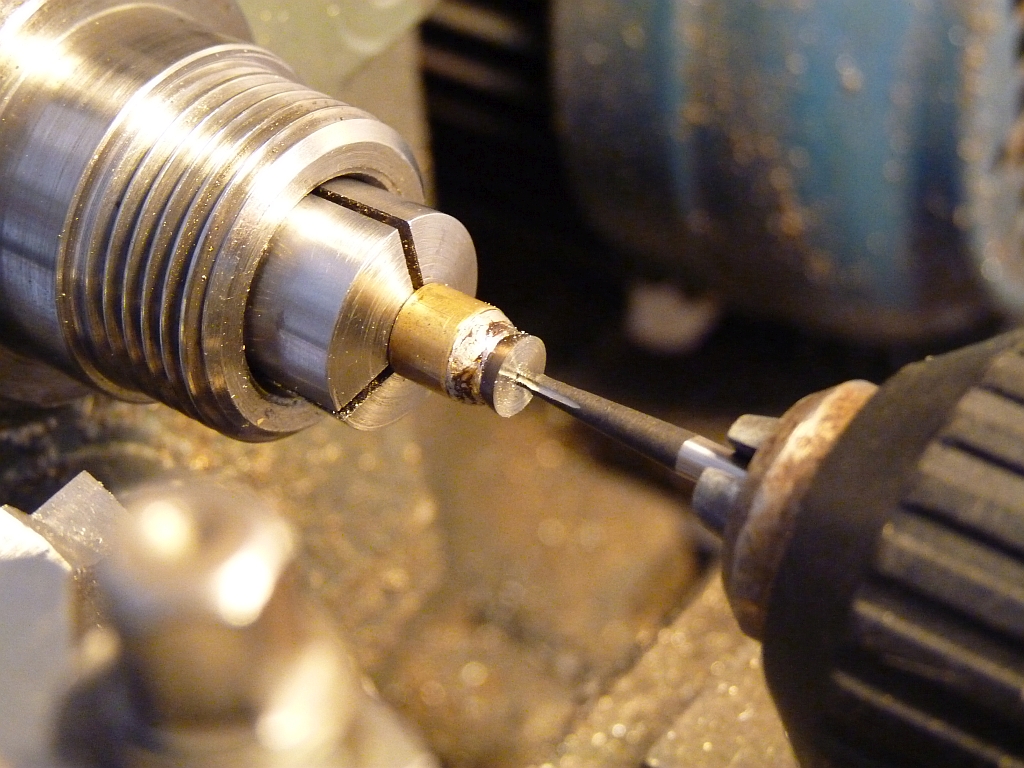
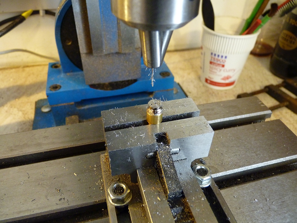
One of the halves had to have a small slot milled in it to fit over the flat spring.
All in all the weights were a really fiddly job!
Just a couple photos of the finished governor assemble ready for fitting to the cylinder. I was really glad to finish this!
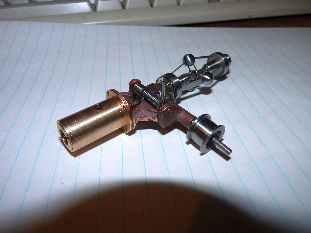
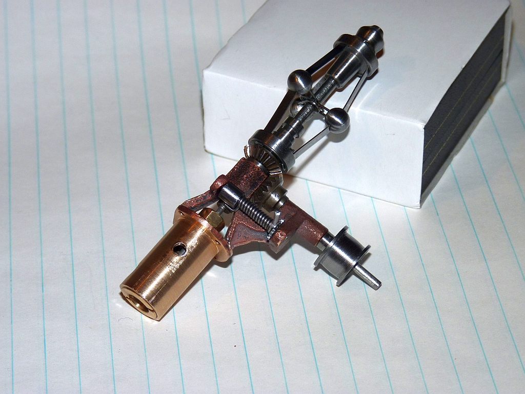
I don't think the governor would have worked as the spring strips seemed far too stiff for the ball weights to fly out at a reaonable speed but it looked good!
I think that is about it, or at least what I can remember. I did make the proper 3 cock water gauge for it and one or two other bits such as the steam manifold.
Gary did send me some photos of the completed traction engine and he had made a superb job of it despite his limited facilities. He did end up buying a small mini lathe and a small mill to make some of the parts himself.
I think Gary did steam it successfully a couple of times but he then contracted some really nasty illness that left him badly disabled and he finished up selling it as he just couldn't move it, especially as he lived in an upstairs flat. A real shame after all the hard work he had put into it.