2
12/1/2012
Wow, yet another year gone by!
Before taking the boiler to the club for our boiler inspector to give it the once over, I decided to fit another cross stay over the top of the firebox to be on the safe side. This was made in the same way as the originals - a length of bronze bar threaded at each end and a double threaded nipple screwed into the firebox wrapper and then caulked. I did look at putting another set of stays towards the bottom of the firebox, below the tubes, but didn't in the end as they would be too close to the foundation ring to make a great deal of difference.
I took the boiler to the club along with my hydraulic test rig and had a chat to the boiler inspector. He agreed with my suggestion of dropping the working pressure to 70psi and we also agreed to reduce the period between hydraulic tests from 4 years down to 2 because of the age and construction of the boiler. We therefore gave it a test to 140psi which it passed with no problem.
With the boiler sorted it was now time to tackle the cylinders and motion work.
First job was to remachine the cylinder port faces. This was done by mounting the cylinders in the lathe and skimming the faces with a fly cutter. I think it's easier to get a good finish with a fly cutter than using an endmill.
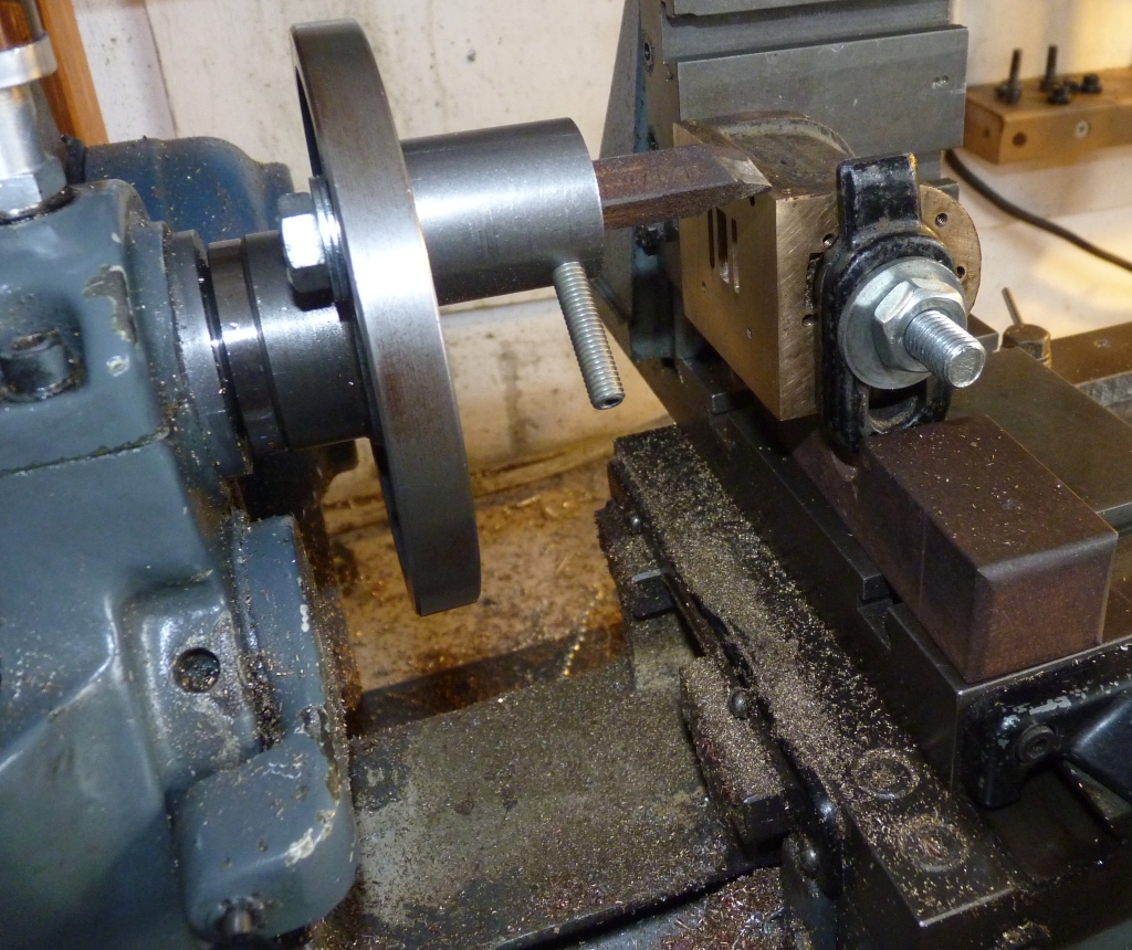
Skimming the port faces with a fly cutter
The edges of some of the ports were a bit rough so I trued these up as best I could with a 2mm carbide endmill in the small mill which is ideal for little jobs like these that don't demand heavy cuts. As it happens, I only needed to take a few thou off to get a good clean edge to the steam ports. The exhaust ports were not so good but that doesn't matter really as they don't serve any purpose in the valve timing and are just a hole for the exhaust steam to escape through!
Truing the ports
The valves were tackled next and I thought I would have problems with them matching the now slightly oversize steam ports. One proved to be just wide enough to fit the ports but the other was too narrow and needed a thin strip of brass silver soldering onto one edge and then machining down to the correct length. Both of the exhaust cavities were considerably narrower than they should have been and just needed widening. This meant that the valves would have originally had exhaust lap (the cavity was narrower than the distance between the ports) which would have made the ports open to exhaust very late and wouldn't have helped the free running of the loco (assuming it ever did run).
The cylinders could now be fitted to the frames again along with the valve chests and the steam and exhaust pipes. The original graphite packing on the pistons was a bit loose in the bores so this was replaced with some square section PTFE packing which I haven't tried before. It will be interesting to see how it performs. The cylinder covers etc. were all fitted with new gaskets. One thing I noticed when reassembling the cylinders was that a lot of the screw threads are 1/8" Whitworth which dates the loco a bit. Later models would have used 5BA.
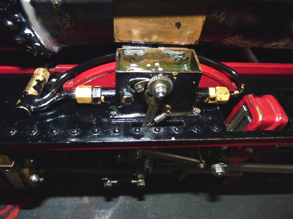
The original drive to the valves should have been the usual threaded brass square nut fitting a slot in the top of the valve with valve adjustment made by screwing the nut along the threaded valve spindle. Usually you can do this by disconnecting the combination lever from the valve crosshead and then rotating the valve spindle but on this loco the valve crossheads are square and run in proper guides on the end of the steam chest. That means that you cannot turn the valve spindles to adjust the valve and you would have to remove the valve chest from the cylinder, rotate the nut around the valve spindle, and then refit the valve chest and try again. What a pain! What the builder had done was to dispense with the thread in the nut and just have a plain hole. He had then put a sawcut across the end of the nut through to the other side of the hole and drilled and tapped for a clamping bolt.
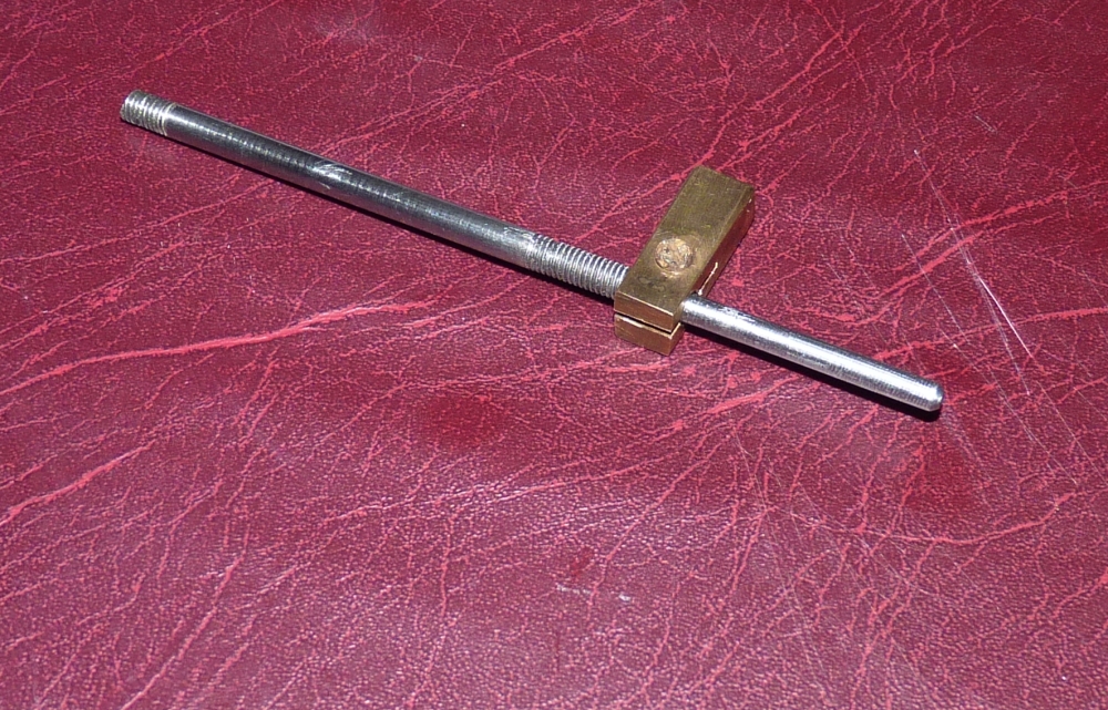
Original valve spindle and nut
The valve spindle was actually threaded as per the drawings so perhaps the builder had a go with the original idea and then changed it? In any case, the nuts on these valves are much longer than those shown on the drawings and still couldn't be rotated even if you took the valve chests off! That's perhaps the real reason behind the design change.
Anyway, the nuts were a sloppy fit on the spindles and in the valves so I decided to make new ones. The slots in the valves were not very square so these were milled out to take 5/16" square brass, a bit bigger than the originals. I wasn't very keen on the split clamp idea, especially on the threaded bit of the old rods, so I made new rods which were plain all along and fitted the new nuts with two stainless grub screws which locked down onto flats milled onto the valve spindles. I'm not 100% happy with this idea but I think it will be better than the originals.
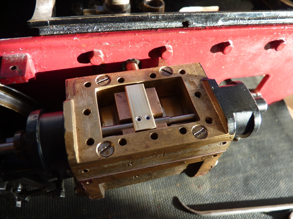
New valve nuts with grub screw locking
Time now to reassemble all the motion work which was not without problems. The steel motion work had been given a coat of varnish or something similar at some time and the steel had started to rust in places underneath. The 'varnish' was stripped off by soaking in thinners so that the steel could be cleaned up again before refitting.
I had problems with the slide bars when I tried to refit them as they were miles out of line with the crossheads! I had to machine some of the ends that fitted to the cylinder end covers and the motion brackets to get them to line up properly and fit shims to the others. I began to think that I hadn't put the cylinders back correctly but the slidebars must have been a poor fit to begin with. One crosshead looked as though it had only been touching the slidebars at two corners. There were one or two tight spots in the valve gear after fitting which were traced to a lack of clearance between the front of the combination levers and the slots in the valve crossheads. Just needed the slots extending a bit with a file.
After roughly setting the valves I gave the chassis a run on air. It ran very well on about 10psi and things were looking good. There was a bit of a knock coming from somewhere though and using a bit of plastic tubing as a stethoscope I traced it to the centre axle. I did notice that the left hand expansion link didn't seem to be moving as far as the right hand one and it's motion seemed a bit jerky, so I took the chassis back into the house to investigate. Waggling things about showed that the left hand return crank was loose on the crankpin and could be moved quite a bit. I thought the taper pin holding it had come loose at first but it proved much worse than that. The crankpin was loose in the wheel! Oh @?%$! It wasn't loose enough to rotate completely but just moved a few degrees one way or the other. Aahh! Why do I take on these jobs? I must be mad.
There was nothing for it really but to take the wheel set out of the frames which meant dismantling half the motion again. Also, the axle pumps are driven off this axle so the ecentric straps had to come off as well, plus half the brake rigging.
I've managed to get the wheels out and it appears the crankpins are fitted through the wheel boss and then rivetted over on the inside. Funny enough, this loose crankpin looks as though someone has tried to tighten it up as the end is not as nicely rivetted as all the others and the paint is chipped off. It seems that this may not be a new problem.
If the crankpin was just a press fit, it would be easy to take it out and Loctite it back in but it makes it difficult with the end being rivetted over. Getting it out will be difficult unless I press the wheel off the axle which I want to avoid if possible. One alternative is to tighten it up by peening over the end again and drill for a pin through the wheel boss into the crankpin to make sure it can't rotate again. Another problem is that the end of the crankpin is drilled to take the pin that locates the return crank so the crankpin's got to be set in the correct position. Problems, problems, problems! (as Marillion said)
18/01/2012
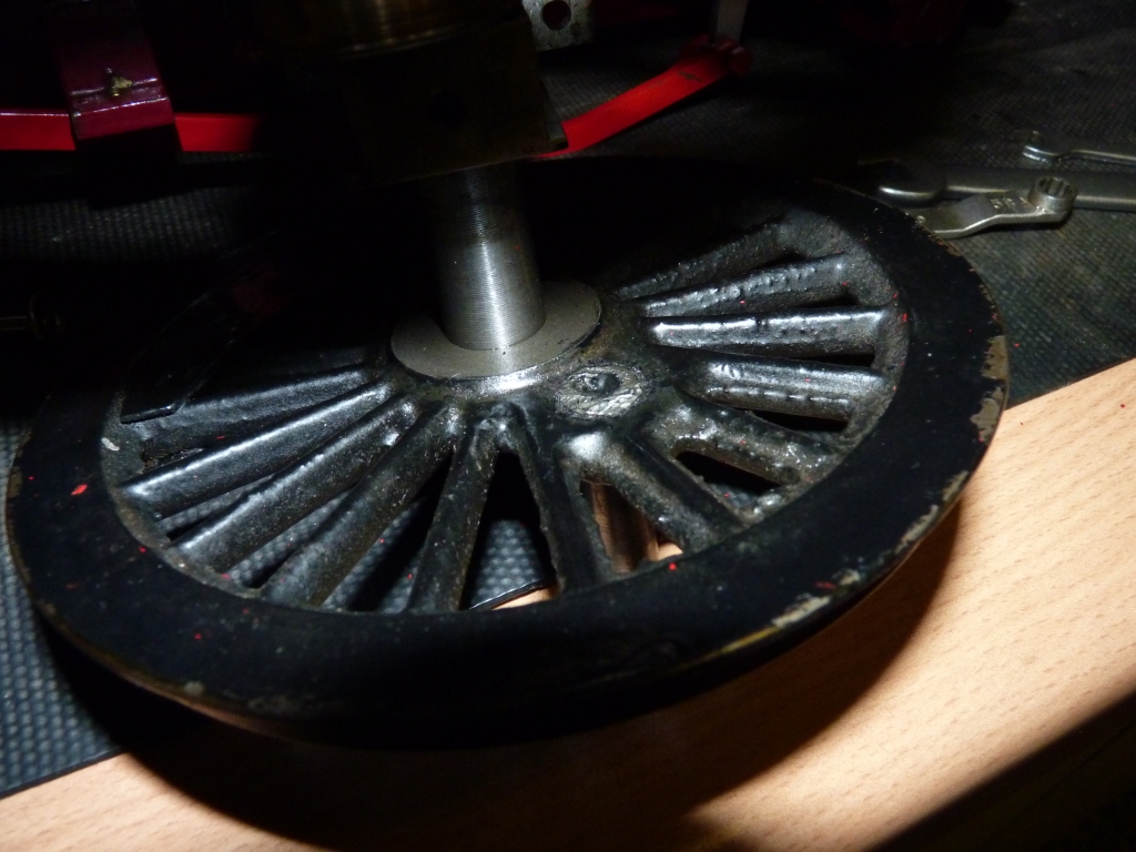
After sleeping on the crankpin problem I decided to try grinding off the rivetted end of the crankpin so that I could hopefully get it out. This proved fairly easy with a carbide burr in the dremel and I managed to get the crankpin out without damage. Fortunately, the hole in the wheel boss had not been countersinked and the end rivetted into that, otherwise I don't think I could have removed it so easily. This now gave me the opportunity to use Loctite to secure the pin into the wheel, so that just left the problem of locating the crankpin at the right position in the wheel. I decided the easiest way was to use the lathe as a jig. The wheels were located in the gap between the sides of the lathe bed and the good crankpin rested on a block of metal so that the line between the crankpin and the axle centre was more or less horizontal (the return cranks and the eccentric rod drive bolts had been refitted to the crankpins before this). Suitable spacers were placed on the lathe cross-slide and a drill shank chosen to fit the gap between the spacers and the bolt on the return crank. If the wheel was now reversed, the loose crankpin could be rested on the spacers and the drill shank to set it in the same position as the fixed one. The loose crankpin could then be Loctited into the wheel and set in the right position.
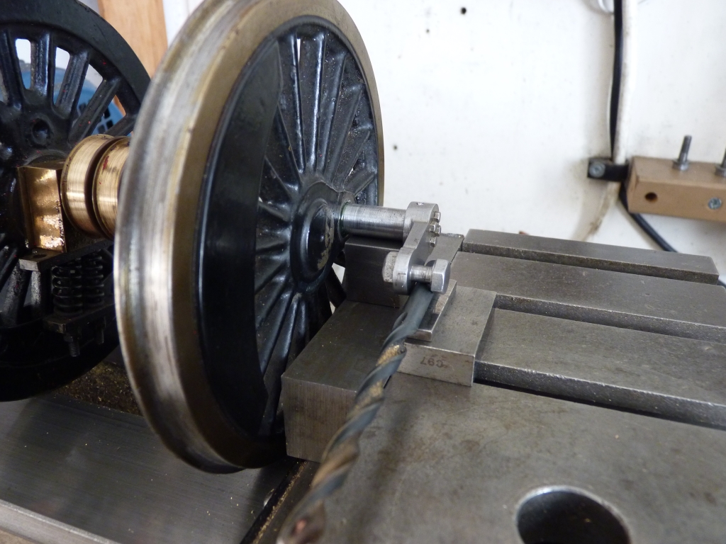
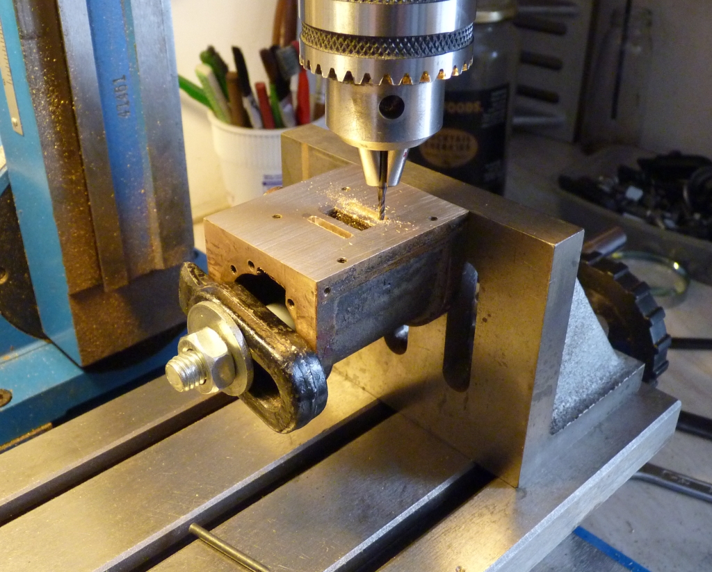
I decided to pin both crankpins as well to ensure neither would move again. The wheel boss and crankpins were drilled to take a 1/16" silver steel pin which was also Loctited into place.

Drilling wheel boss and crankpin for pin
Once this was done I could refit the wheel and reassemble the motion. Another test on air was done which showed one of the valve settings to be very slightly out. This was adjusted and the chassis then ticked over nicely on 10psi of air at about 60% cut off. That's good enough for me!
Next job is to refit the boiler and try running it on steam.
07/05/12
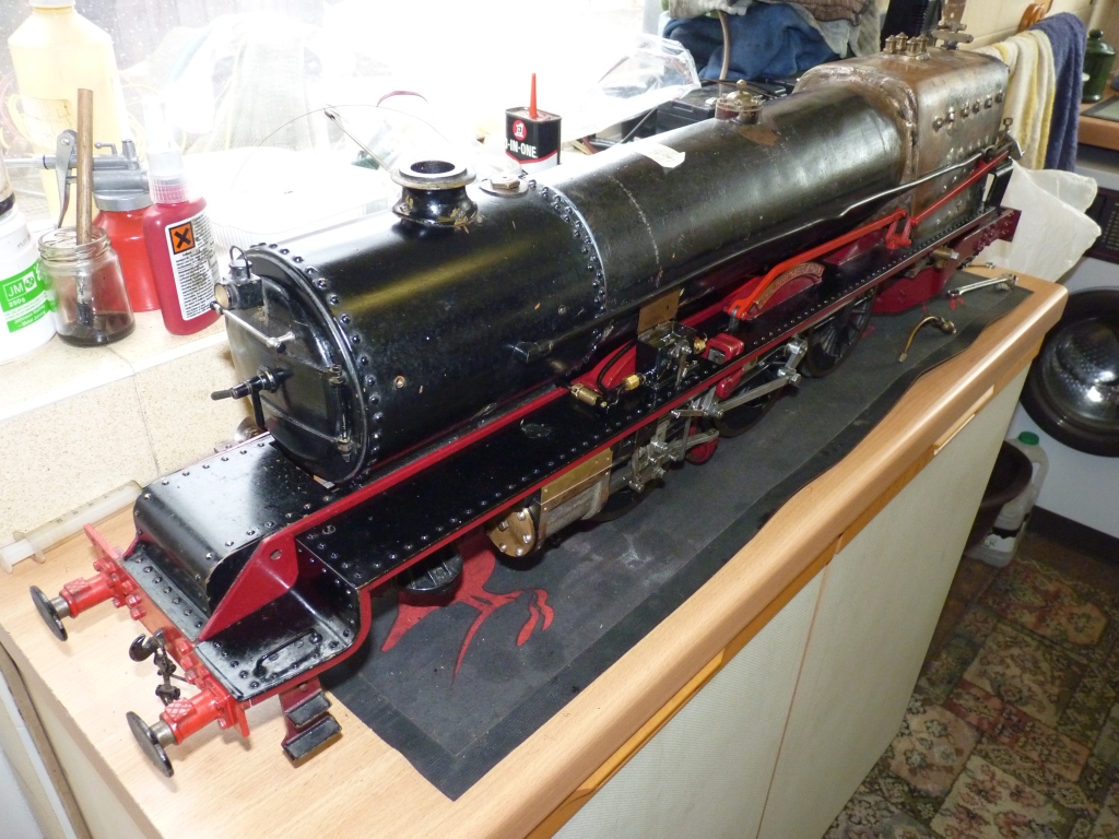
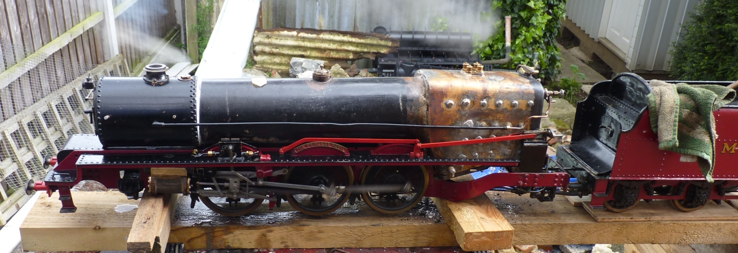
A long time with nothing done to the Princess due to other things but over the last couple of days I've temporarily refitted the boiler (minus cladding). Fitting the grate and ashpan was a pain as they are permanently fastened to the foundation ring of the boiler. The centre section of the grate hinges down so that you can dump the fire into the ashpan. The grate was actually too narrow and I had to add another firebar each side to fill a big gap! Any small coal would have just fallen straight through.
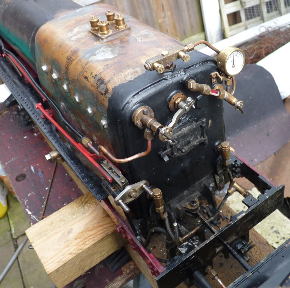
I made one or two 'mods' as I refitted the valves etc. The bottom fitting for the gauge glass had a screwed in stub where it screwed into the boiler rather than a fixed threaded boss. I wasn't very keen on that so drilled out the fitting and silver soldered in a threaded boss. I also fitted a length of my favourite red stripe gauge glass rather than the original plain glass. The gauge glass is steeply angled so the actual range is very limited. It's also very high up on the backhead so the water level in the boiler will be high which may cause priming if the glass is full to the top.
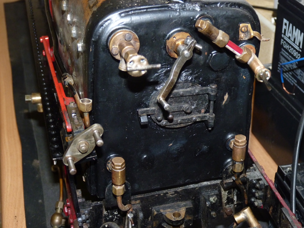
The water plumbing is a bit of a rats nest and I'll probably alter at least some of it on final reassembly. The loco does have an injector which feeds into the same boiler clack as the axle pumps. I haven't tested that yet so I don't know if it works. I didn't bother refitting that at this stage.
The lubricator comprises a single ram driven in the centre with a cylinder at each end and didn't seem to pump any oil so I took it to bits to have a look. One end of the pump had a ball and spring non return valve fitted but the other did not so I don't think that end was working at all. The outputs from each end are then combined into a single check valve before going to the cylinders.
I put it back together with the missing ball and spring and it now seems to work ok.
Yesterday I managed to fire up the boiler and run the chassis on steam, possibly the first time for at least 30 years. Quite a few little problems manifested themselves during the steam up but nothing serious. The gauge glass leaked like a sieve from the top fitting despite tightening it up as much as I dare. I think the silicon rubber sealing ring wasn't thick enough so I'll replace that. One or two of the valves leaked but the biggest problem was that the blower didn't work at all. I later found that the valve was completely bunged up with 'goo' used to seal the pipes to it. Despite these problems I managed to get pressure up to about 40psi, enough to run the chassis which ran very well indeed. The axle pumps work very well as I found out when the bypass connection wasn't tight and I got liberally sprayed with water! The pumps fill the boiler very rapidly. The tender handpump seems a bit restricted in movement by the filler opening so I'll have a look at that. The pressure gauge is fed from a steam valve which I don't like so I'll plumb that directly to the steam turret. At the moment the blower valve is a separate globe valve hanging off a pipe from the turret. There's a valve bolted straight to the backhead that is meant to be for the injector but I think I'll use that for the blower and use one of the valves on the turret for the injector. I found out later that one of the turret valves is very loose in the threads in the turret so that needs sorting out.
All in all, a promising first run. The boiler was still tight under steam, although only at 40psi, but should now be ok. The chassis runs nicely and will notch up well. I'll get all the little snags sorted and then give her a run at full pressure. If still ok, the boiler cladding can be refitted and given a lick of paint. Then it's down to the track!
09/05/12
Today I replumbed the blower to the old injector valve and added a threaded boss to the steam manifold for a direct connection to the pressure gauge. I also rethreaded the turret 7/32 x 40 for the two steam valves mounted on it (the originals were only 3/16" x 40). This will mean cutting off the old bosses on the valves and silver soldering in new ones. One of the originals was a very poor fit in the turret so better safe than sorry.
I decided to give the boiler another steaming but the heavens decided to open as soon as I started so things got rather wet! This time the blower worked fine and there were no leaks from the gauge glass after fitting a thicker sealing ring. There's a lot of condensate comes out of the blower when first turned on as it's an external pipe rather than one through the boiler. Pressure soon picked up and I kept a wary eye on the gauge as I wasn't sure what the safety valves would blow off at. I did dismantle one earlier and thought the spring looked rather strong so I unscrewed the adjusters on all of them as far as I dare. When the gauge got to nearly 70psi I decided to open the regulator and the next thing the gauge was heading towards 100psi!! I quickly opened the firedoor, shut the blower and pumped cold water into the boiler which brought the pressure back down again. The safety valves showed no signs of lifting even at that pressure so god knows what they would have opened at as they were originally set, possibly at least 200psi ! Another reason for thinking the loco has never run. Mind you, the boiler originally leaked so badly that I doubt if it would have been possible to build up any significant pressure.
I ran the loco for a bit being very careful not to let the pressure get above 70psi. It ran very well but I don't think the lubricator is doing very much. There was a bit of a 'squeak' from the exhaust when just ticking over which suggests a lack of oil. The fire seems to burn well although the blast nozzle looks quite small for the size of the cylinders. If the loco runs ok on the track I'll leave that as it is.
Dropping the old fire proved to be a right pain. The centre section of the grate doesn't drop down very far before it hits the ashpan so there's only a small gap to push the ash and cinders through. I don't think there's anything that can be done about that though without a major redesign.
When things had cooled down I removed all the safety valves and had a look at one. The springs are very short due to the length of the body but I managed to find some thinner gauge stainless springs about the right size. I tested one of the modified valves using my injector test boiler but the lifting pressure was still much too high and the valve leaked quite badly. Looking at the seat for the ball showed it to be conical rather than a square edge which would make sealing difficult so I remachined it with an endmill and reamed the hole to give a nice square edge for the ball to seat on. I also machined the seat a little deeper than before to hopefully reduce the spring pressure on the ball and lower the operating pressure. On the next test the valve lifted at about 70psi which was definitely luck rather than judgement! Just got to do the other three valves now.
13/05/12
I modified the other three safety valves and set them on the test boiler. They're fairly 'lazy' in operation and lift gently and the pressure needs to drop about 10psi before they shut properly again. They are only straight non pop valves so that's to be expected. One day I'll get around to making the semi pop design by Gordon Smith!
I steamed the loco again with better results from the valves this time.The lubricator definitely isn't working properly so I only gave it a quick run.
I'm still not happy with the safety valves as they allow the pressure to climb a bit more than I would like. I know you are allowed a 10% increase on the accumulation test of the boiler but I prefer to keep it less than that. The valve seats were reamed out to 9/64" diameter when I altered them but I reckon they'll stand taking out to 5/32" with the 3/16" diameter balls so I altered them again. I also filed the notches in the adjusters as deep as I dare to increase the area for the steam to escape.
I stripped the lubricator again and remachined the seats for the non return valves as I don't think they were sealing properly. On one end, the bore in which the ball operates was not concentric with the valve seat and I don't think that ball was seating at all. The ram isn't that good a fit in the body either so I managed to fit a 1/8" diameter O ring on each end of the ram by machining a groove with a narrow parting tool. If that doesn't work I'll have to perhaps make a new ram which will mean turning one down from larger diameter material as the bore is a few thou over 1/8" diameter.
I also modified the blower valve by soldering a 1/8" copper pipe into the end that fits into the boiler. This curves up to the top of the firebox so should ensure drier steam for the blower. Before, it was carrying water through with the steam due to the inlet to the valve being quite low on the backhead. As mentioned before, the valve was originally for the injector but wouldn't have been much use for that due to the water carry over which would just keep knocking off the injector (assuming it ever worked).
Tomorrow I'll steam the loco again and see if the improvements have helped at all.
18/05/12
The next steaming was quite successful. The safety valves are better but may still struggle to keep the pressure within limits if the blower is really opened up as it's very fierce. The bodies are threaded internally 1/4" x 40 but would stand going up to 9/32" or even 5/16" with a 7/32" or 1/4" ball. The lubricator was much better and delivered oil as it should.
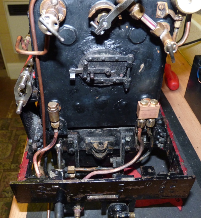
I decided to refit the injector now so I could take the loco to the club for a steam test and maybe even a run around the track. There are only two clacks fitted on the backhead and originally the injector fed into the same clack as the axle pumps with the hand pump going into the second clack. I didn't like that idea at all so made a 'double' clack to replace one of the single ones and the hand pump and the axle pumps were plumbed to this, leaving the second single clack for the injector. I modified one of the original steam valves on the turret by drilling out the passages and fitting a larger spindle to increase the steam flow.
I tried the original injector on my test rig but it didn't work very well. It doesn't lift and is very difficult to get started. It will run once started but more water comes out of the overflow than from the output! It wasn't possible to stop this by reducing the water flow - the injector just cut out. I tried adjusting the steam cone with limited success - it would run once ok started but still with a lot of overflow. I don't know if it's a home made job or a commercial one but either way it needs work before it will work properly. For the time being I fitted a Gordon Chiverton 12oz one which works fine.
I also made a new flexible hand pump connection between the tender and the loco using a length of plastic hydraulic pipe fitted with homemade barbed fittings at each end. At least the loco and tender should go around curves now! At the same time I fitted an injector water valve to the tender as it didn't have one before. The feed just went straight from the tender tank to the injector. Mind you, no water came out of it as the fittings were again bunged up solid with jointing compound!
I steamed the loco again today to check the injector and the new hand pump connection and they were fine. One problem now is that the regulator is very stiff to operate uder pressure and there's nothing I can do about that without dismantling it again which will be a pain. I'll have to sleep on that one.
I'm going to take the loco to the club on Sunday for a steam test and a run if possible so the front bogie and the pony truck need to be fitted again. I fitted the pony truck tonight and found a snag with that. The truck is fitted with a hook that goes over a bar across the loco frames. This is to stop the truck dropping down when the loco is lifted up which would put a lot of strain on the pivot pin. I found that this hook fouled the bottom of the ashpan and prevented the truck frame from moving vertically. The axleboxes are solid with no springing - the whole truck should move vertically against two spring loaded plungers attached to the loco frames. As it couldn't do this because of the hook fouling the ashpan, the pony truck was effectively rigid and had no suspension. I eventually took the hook off when I found that the brake rod that passes under the truck stops the truck dropping down so the hook was not really necessary anyway. Problem solved.
20/05/12
I took the loco to the track today with mixed results! The steam test was ok but the run on the track was a bit of a disaster. I managed two laps and then gave up. The loco was really tight and struggled to get around the curves and wasn't much better on the straights. The front bogie came off a couple of times as well. It felt as though the wheels were over gauge so when I got back to the steaming bays I checked the wheels to see if there was any side to side play on the track. The bogie wheels were solid and couldn't be moved sideways at all. The leading and trailing driving wheels had a bit of side play but the centre drivers were tight. Looking back, I did notice that the wheels 'squealed' a bit when I took the loco up the run in track to get onto the main circuit. Also, the lubricator didn't seem to be working again so that needs some attention but that's a minor problem compared to the wheels!
My first thought was that the back to back dimensions for the wheels were too big so when I got home I took the front bogie off and checked. If anything, the back to back dimension was slightly small. I then checked the leading driving wheels and that dimension was quite a bit undersize (3.25" - it should be 3.281"). Looking further, it looks like the wheel profiles are all wrong. The flanges are too thick and the root radius (the radius between the tread and the flange) is too large on some of the wheels. In fact, all the wheels seem to have different profiles! I think the flanges must have been wedging themselves between the rails which was why the loco was so tight on the track.
It looks like I'm going to have to reprofile all the wheels! That's going to be a right pain as it will mean stripping the chassis down again to remove the driving wheels. Oh well, at least the boiler's ok and I can now refit the cladding and get it painted.
The forecast for next week is warm and sunny so I'm going in the garden and forget about locos for a bit!
< Previous Page....... Next Page >